
Firstly, the “Red Slug”

The “Red Slug” antenna, as it has been nicknamed, is a ground-mounted quarter-wave vertical antenna with a feed point that is red (hence the name). It consists of four parts,
- A ground stake with an M10 thread on top of it
- The “Slug” feedpoint with an M10 hole at the top and bottom and an SO239 socket on the side, where a tab to connect radial wires can be/is mounted.
- A 5.6m extended-length 14-section telescopic whip with an M10 threaded bolt on the bottom of it.
- Radial wires (8 x 3metre silicon rubber-covered hook-up wire is what I use).
All of these parts can be purchased separately from the various Chinese online marketplaces or even on Amazon and eBay.
They are sold individually or as a pack. My advice is DON’T BUY THE PACK – it will cost you more than shopping around and buying the parts separately. The supplied set of radial wires made from computer ribbon cable is destined for the bin in any case. They don’t work. Make your own set of radial wires from hook-up wires. My sets are eight 3-metre-long lengths of wire, one end of them all soldered together in a crocodile clip. You will need to supply the coax feedline cable to go to your radio. This will need a PL259 plug on one end and whatever your radio (or the external ATU) needs on the other end.
When buying from Chinese dealers, since the 1st of July the EU has removed the “de minimus” rule which allowed low value items to come into the EU without paying any duty and in so doing, vastly reducing the workload on the customs departments. As of July 1st 2026 a blanket €3 import tax has been applied to low-value items (even those costing less than €3), but it should be noted that buying two of the same item, does not incur a €6 import tariff rather a €3.20 one, so if considering building this antenna with parts from China, perhaps get together with a friend and build two or more, to reduce the overall import costs. Another option is to buy from a Chinese dealer’s European warehouse; the import tariff does not apply as the goods are already in the EU.
And now the Parasitic reflector addition
Once you have this simple antenna working, you might want to consider how you can make it “better”. “Better”, we tend to think of an antenna having gain to increase received and sent signals. There is no “magic” amplification in an antenna. The only way you achieve “gain” is by reducing the transmission area or directing (or receiving) a signal better in one direction. To do this with the vertical antenna, we use a reflector positioned behind the antenna. This reflector is not connected to the radio or the vertical antenna (some phased arrays do have connections). This reflector is a “parasitic” element, in the same way as a reflector on a Yagi beam is.
The reflector is made of another 5.6m telescopic whip and ground peg; however, as we short these together, we do not need another feed point “slug” but rather a long-nut-like, metal conducting adapter with a female M10 hole at both ends. Let’s not forget the radials as well. These need to be the same as the ones used with the 1/4 wavelength antenna, which we will now call the “Driven Element” of this “vertical beam”. The reflector needs to be longer than the driven element and spaced at a quarter wavelength behind the driven element. As this antenna can be used on all ham bands from 20m to 10m the lengths and gap distances should be calculated for all the bands that you want to use this antenna on. (see chart at end of this article).
The equations to calculate all of these needed factors are:
- Driven element in metres (as used in the basic quarter wave vertical configuration): 71.5 / Frequency in MHz
- Reflector height in metres: 7% more than the driven element
- Distance between driven and reflector elements (same as point 1 – wavelength/4).
Initial Test:
Once the waited-for ground spike arrived, I managed to set up the 1/4 wavelength vertical and the reflector in my garden, between the apple trees. Not an ideal situation but good enough for this initial test.
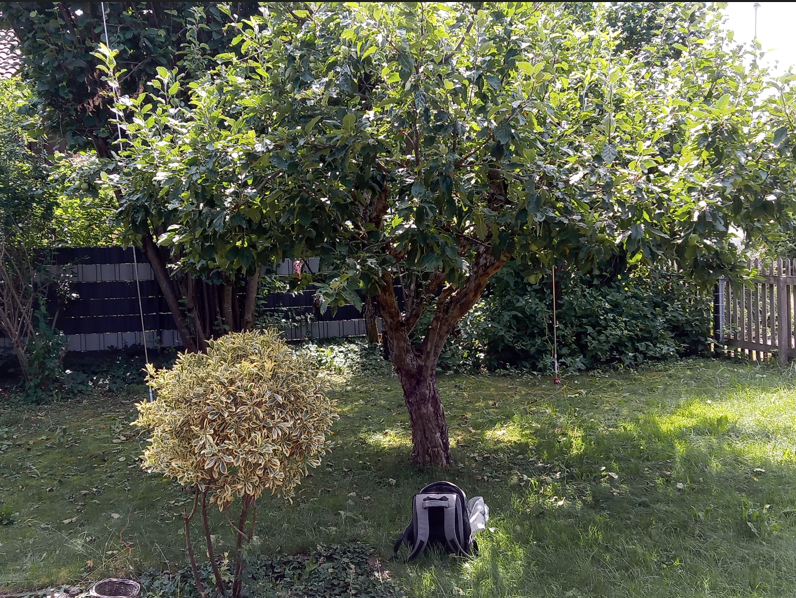
I set up both telescopic whips, spaced a quarter wavelength apart, each with their own 8 radials and connected my little G106 QRP radio. Tuning the 20 metre band, I came across an S5 signal from an ON3 station which would be about in the direction that the array was pointing. To test, I decided to simply unclip the radials from the reflector, hence making it ineffective, and as I did this, I could hear the signal drop on the radio. I went back to the radio and the S5 signal was now indicating S3. I re-attached the radials and the signal came back up to S5!
This is not a truly scientific test, as always there’s a question as to whether conditions were affecting the results. I don’t think so, given that I could hear the signal drop immediately as I disconnected the radials from the reflector.
I performed several more tests in a more open environment at different times of day over a longer period of time and but my findings do seem to echo the fact that a simple parasitic reflector can provide some good directivity to the quarter wavelength vertical antenna.
Whether a 2 S-point improvement is truly correct, I have my doubts; however, even a 1 S-point improvement would be welcome given that the G106 is not the greatest of radios; it’s likely that its meter is not correct. Audibly, however, it was the difference between a clean, easy-to-listen-to signal and one in the noise.

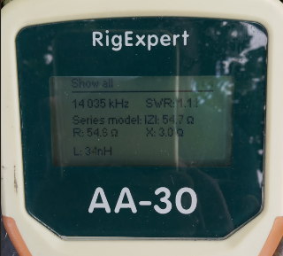
Analyser readings without & with reflector.
From the readings shown, it should be noted that adding a reflector affects the driven element, changing its point of resonance.
Here are my results of tests done twice to ensure consistency (which, with readings from both actions within 0.01 of each other, I think I can say I achieved).
Test plan:
- Erect just the 1/4 wave vertical without the reflector.
- Measure on analyser, record readings.
- Put up reflector
- Measure on analyser, record readings
- Retract and unscrew from base the reflector whip, laying it on the ground.
- Measure on analyser, record readings.
- Erect reflector again
- Measure on analyser, record readings.
These were the results recorded:
Without Reflector:
Frequency of lowest VSWR 14.195 MHz
VSWR 1.2:1
IZI 47 Ω
R 46.2 Ω
X -8.2 Ω
C 1343 pF
With reflector in place:
Frequency of lowest VSWR 14.035 MHz
VSWR 1.11:1
IZI 54.6 Ω
R 54.6 Ω
X 3.3 Ω
L 40 nH
So, I think we can say the reflector is affecting the driven element. My friend, Rob DM1CM, designer & owner of the portable-antennas.com website, helped me by modelling my set-up:

When modelling this antenna, an interesting fact appeared: shortening the distance between the two elements, you come to a point where the reflector starts to act as a director, and the direction of transmission is reversed.
Following some practical tests, the chart below gives the values that I use. The top line is for when I use JUST the driven element on 40m using the loading coil, which is also sold through the same Chinese outlets and works fine.


You must be logged in to post a comment.