
Please refer to www.antennaengineeringdl4kcj.de for an extensive discussion on the theory of magnetic loop antennas and for multiple different designs from DL4KCJ. The inclusion of graphics and text here recognises the rights of the original author’s text in German from that site.
DL4KCJ Antennas use a different approach to magnetic loop antennas than you normally see. I have this “ASL-110” model located simply in the loft space of my garage and for such a small antenna, it works remarkably well. It has the restriction that all magnetic loop antennas have very small frequency bandwidth and as I have no remote tuning, this means it becomes a fixed frequency antenna on just one band even though it can operate on all bands from 80m through 10m.

Fig.1 shows an asymmetric Loop for the 40 + 80m band
The ASL110CC was the test winner of 10 tested Loops in terms of cheapest construction using fixed Coupling and creating the best field strength readings
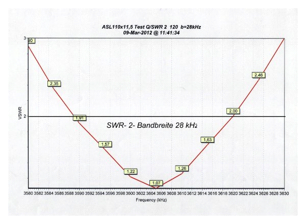
Fig. 2 shows the SWR curve of an equally sized loop with inductive coupling.
The bandwidth is 30% (9kHz) narrower than the loop in Fig.1. The reason is the weaker coupling due to the use of an inductive coupling. By using a fixed coupling, the TX bandwidth is 30% larger than in the version in Fig.2
This also causes a field strength Advantage of 3 dB!
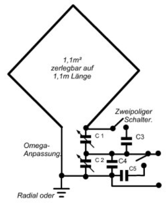
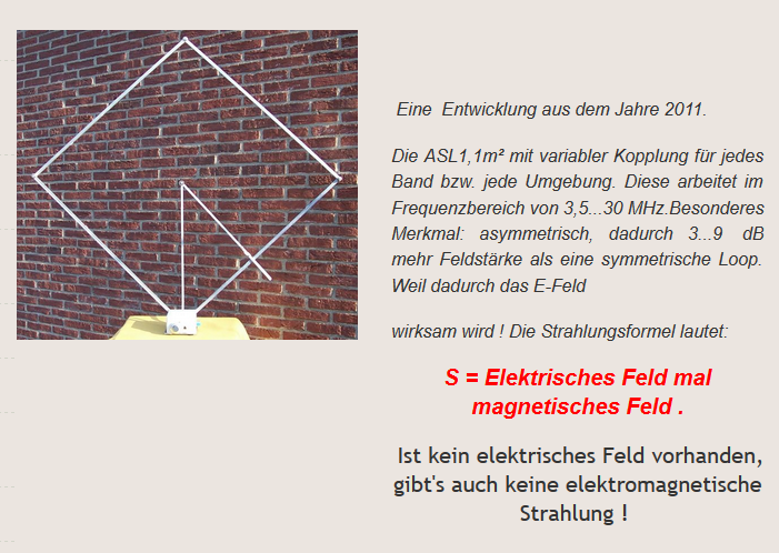
Fig. 3
Asymmetrical square loop with square conductor cross-section. The test winner of a screening of 10 loops with respect to the cheapest coupling or largest field strength. Operation for the 40 + 80m bands.

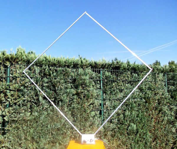
Fig. 4
In addition to the above, this is the arrangement for the 20m band. This is created by switching C1 + C2. Again, there is a strong coupling with the TX through the series connection.
For the 10 + 15m band to be possible, the loop area has to be reduced to 82cm². On the ASL-1 80m-10m loop (below) this is achieved using a shorting bar.
From the antenna lab of DL4KCJ.
The new ASL110 CC for the range of 20 … 80m, is available from mid-May 2012 Pmax.:100W non-detachable, Transport length 1.1m. The use of a Vernier knob for adjustment makes it easier to tune. Material: 11.5mm square aluminium tubes each 1.1m long.
How the ASL110 CC works.
In search of the optimal loop, 10 loop arrangements with different conductors and matching circuits were examined. The square loop with square conductor cross-section proved to be the best, in asymmetrical operation and with omega adjustment. For high efficiency, it uses a strong coupling of the TX lead to the low-loss loop. With inductive coupling, no strong coupling was possible, which is reflected in a high load. This in turn creates a high voltage and current thereby making the variable capacitor significantly more expensive. An asymmetric loop is more than 3 dB better than a symmetrical Loop because the asymmetrical loop works against the earth and/or radials. The symmetrical loop radiates in a no-earthed environment, the so-called HF-Swamp. A lot of energy in the near field is absorbed or wasted. In the near field of the loop, there is a high reactive power, however, which causes active power losses in distributed earth systems. The individual capacitors form an omega match for the relevant bands. For the 20m band, only the rotary capacitors C1 (tuning) and C2 (adjustment) work in series (see Fig.4.) On the 80m band C3 (bandspread) and C5 will be switched in. On the 40m band C4 must be switched in. For 10 + 15m band operation the loop circumference must be reduced to 3.28m using the sliding shorting bar. This arrangement is very effective. DL4 KCJ May 2012
Measurements and calculations for the ASL110 CC on the 80m band.
First, the natural Qn must be determined: For this purpose, the voltage at C1 to ground, minus the feed voltage, is divided by the voltage at C2. Here we get Qn = 11.6. Thus, the rotary voltage Uc1 is 11.6 times greater than Uc 2, minus the feed voltage. That is at 100Weff = 100Vs so 1060Vs. A standard radio variable capacitor is adequate at this voltage. The inductance was measured and is 3.95μH. The loop current is calculated as follows: Uc1 / XL, the inductance corresponds to an XL of 89 ohms. So you get 1060/89 = 12 ace. The 11.5mm² tube is sufficient for this current level as predicted for the ASL110. The loss here is: 1 / Qn, 1 / 11.6 = 0.07 = 7%, which corresponds to an efficiency of 93% on the 80m band. If the load was twice as high, the voltage and current would also be twice as large in the loop. The effectiveness only increases by 2.6%, which is meaningless in practice.
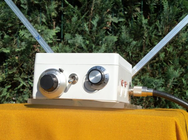
The ASL110 CC 20 … 80 m in operation at 1.5m high and consists of four rods of 1.1m in length.
The tuning/adjustment box of the ASL110 CC 10 … 80 m with a Vernier knob for easy adjustment on the left. Right: Fine adjustment
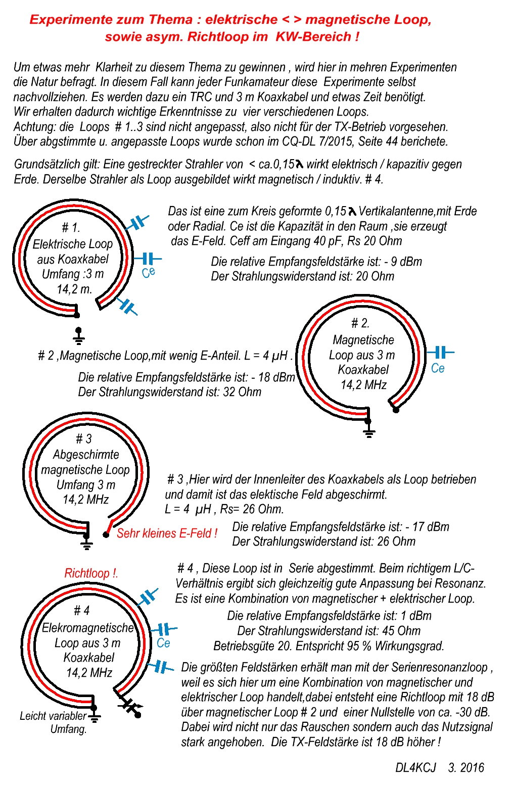
The following reference documents are an image of a document and do not allow simple computer translation. They are included here in German for completeness.


You must be logged in to post a comment.