
HB9SL – An effective antenna for portable QRP?
From various Internet articles the antenna described here is said to be ideal for long-distance communications on low power, it supposedly wins over a quarter-wave vertical with dozens of radials, an end-fed half-wave vertical and a high dipole. Developed by HB9SL (Fritz Demuth, SK) it’s called the ” Vertically Polarized 2 Element ” VP2E antenna.
 The HB9SL antenna has the following features: it emits at a low angle towards the horizon, about 26 ° (effectively 20 – 40 °), it has vertical signal polarisation, and the antenna gain is about 3 dBd! The antenna does not require a Balun and, most importantly, high masts. The radiation pattern is almost circular, the maximum radiation/gain point exists in the direction of the longer wire – i.e. away from the feed point. The following article is related to a 14MHz version of “Vertical Polarized 2 Element”, using as a mast a 4.2 Metre fibreglass pole.
For 14MHz a run of wire with a length of 20.8 meters is fixed to the top of the mast exactly at the midpoint. Wires go down and are fastened with cords to pegs with antenna ends raised off the ground. On one side, a distance of 6.3 meters from the end of the antenna, a break is made, a plate is inserted to form the insulator and a 50-ohm cable is soldered there, no Balun is necessary. In this build, the length of the coax was approximately 7 meters (avoid the coax being a ½λ long). The HB9SL antenna design was modelled with the program MMANA, which showed that sometimes the feed point is better moved a little higher than in the author’s design. Since the weight of equipment is important when portable, chose a wire which is light, flexible and does not tangle or break easily. Due to the fact that the HB9SL antenna does not need a high mast, its wind resistance is low and practice has shown that if the base cannot be secured it is sufficient to add one guy rope (with the antenna wires forming the other two). Please note that any mast used with this antenna should be non-metallic. A fibreglass mast fits this role perfectly. The red arrows in the diagram below show the angles of maximum radiation.
 Measurements of the SWR for this 20m version gave the following readings: 1.5 – 14.0, 1.1 – 14.1, 1.7 – 14.3 MHz. The resonant point is quite sharp, so after constructing the antenna, it must be trimmed to the required frequency range within 20m.
Sizes for other bands. For 7 MHz, you need a mast height of 6 meters, the total length of the antenna wire will be 41.8 meters. The length of the wires to the middle 20.9 meters. The feed point is located at a distance of 15.4 meters from the lower end. The lower ends of the wires must be raised one meter above the ground. Everything else is as described above. For the 3.7 MHz band, a mast height of 7 meters is needed, the total length of the antenna is 79.8 meters. The length of the wires to the middle are 39.9 meters. The feed point is 32 meters away from the lower end of one of the elements. The lower ends of the wires must be raised 1 meter above the ground.
Nadir EY8MM (Tajikistan) – in Jan 2007 built a Vertically polarized 2 Element (VP2E) HB9SL 160m antenna

L1=L2=0.495λ
L3=0.3λ
H1=0.18λ
H2=0.0285λ
He used all standard dimensions except the height. In his case, H1 was 55 meters. Top band conditions were not very good. He only had a few QSOs, the highlight was being called by SU9HP located in Egypt for a new country for him. He states that the antenna showed reasonable directivity (see diagram above). Then he tried the antenna on 80 with an antenna tuner and worked over 80 North American stations! Including OK, MS and KY states. The setup was performed using an IC756ProIII driving an Acom 1000 amp (providing 800W output due to low mains supply voltage).
Another article is on the web from UR5EOT and here is my “improved Google” translation of that Russian article:
Antenna (VP2E) Vertical Polarization 2 Element
The VP2E antenna was developed by the Swiss ham HB9SL. Strictly speaking, this antenna is not a “two-element”, as it is a radiator, whose length is close to one wavelength. Since the radiating element is bent in the middle in a certain way, one of its halves can be considered as an additional element with active energy. But this definition is a minor issue. It is important that the antenna thus configured has a substantial vertical component with a radiation pattern in a vertical plane close to a good GP.
We will talk about the antenna with respect to use on the 80-metre band, although with appropriate scaling, it can be made for use on any amateur HF band. Moreover, for example on 20 meters, its dimensions will be quite acceptable for mounting on a small roof, and it will work better than the equivalent GP antenna.
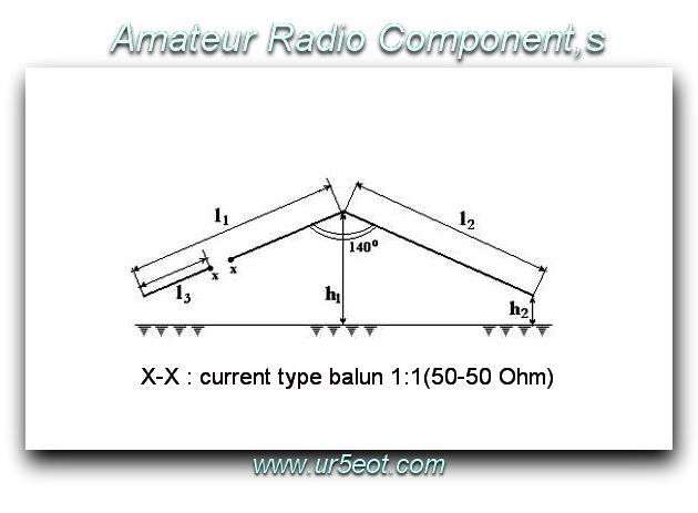
The lengths of the two parts of the antenna at each side of the supporting mast are the same and calculated as: l1 = l2 = 0.492λ. The feed point is located on the left side of the antenna as shown in the diagram below at a distance of l3 = 0.139λ. The angle at the vertex is about 140 °. The height of the mast should be approximately 0.18λ and the height of the small masts supporting the ends of the antenna wires should be about 0.0Зλ.
For the 80-metre band, the antenna wire consists of two parts 39 meters long, and the feed point is 11 meters from the end of the antenna. The mast has a height of 15 m and the small masts 2.3 m each. The input impedance of the antenna when measured was 48 + j2. 8 Ohms, which provided an SWR <1.1:1 at a resonant frequency of 3.78 MHz (ie in the “upper DX window”).
A comparison was made using the ELNEC antenna modelling program of the vertical radiation patterns of three antennas: the VP2E, a Ground Plane with four counterpoise wires and a dipole installed above the ground at a height of 15 m. The diagrams generated were for the gain (in the horizontal plane) corresponding to the maximum radiation for the dipole and VP2E. It was clear that the VP2E had a similar radiation pattern to the GP but at an angle of about 20 ° (close to the optimum angle for long-distance communications). The VP2E provides a signal level of 3 to 4 dB more than the GP and about 7 dB more than the dipole. In the case of the dipole, most of the radiation goes vertically upwards not towards the horizon as needed for DX communications.
The results of the calculation of the horizontal radiation patterns of the same three antennas were calculated for a radiation angle in a vertical plane of 20° (see above). In this case, the VP2E and dipole had similar diagrams. They have approximately the same ratio of emission in the direction of the maximum radiation pattern and its minimum (about -10 dB at the null) but the VP2E provided a higher signal level (approximately 7 dB) in the direction of maximum radiation. As a result, the VP2E and the dipole are inferior in their horizontal pattern to the Ground Plane, which has a circular radiation pattern. The VP2E, however, has a maximum radiation elevation of 60° making it more suitable for DX than either the GP or dipole.
Following on from the “love” of this type of antenna in Eastern Europe, I have found another well-written article from Boris Stepanov (RU3AX), in Moscow in 2016. I have copied the article here and corrected some of the machine translation errors with full respect and acknowledgement given to the original author.
The VP2E antenna:
The low-frequency, with vertical polarization
Antennas with vertical polarization, beginning with the classic quarter-wave GP vertical, have been popular with amateur radio operators. There are several reasons. First of all, most of them have a circular or near-circular radiation pattern in the azimuth plane. This is important in amateur radio for simple antennas, because the potential contacts may be in any direction. Secondly, they usually have in the vertical plane a close to the ground radiation pattern which is important for DX contacts. Thirdly, they are easy to construct and install in a limited space such as on the roofs of residential buildings or a portable site.
But there is one problem – almost all of these antennas require a good “ground”, which is typically implemented as a set of quarter-wave counterpoise wires. Structurally, they seem convenient to be laid directly on the roof of the building but in doing so this causes some losses to the efficiency of the antenna which is especially noticeable when a small number of counterpoises are used. To remove these losses the solution is simple – just do not lay the counterpoise wires on the roof rather lift them to a height of approximately 2 m. But from a construction point of view – either on the roof of a residential building or on a portable site, this is not practical.
The installation of antennas for the low-frequency amateur bands, of course, always brings certain difficulties. As an example, an ordinary GP (Ground plane) antenna for 80m already has a height of about 20 m. Full-length counterpoise wires fitted in a circle would have a diameter of 40 m. This is unrealistic for most amateur radio operators using roofs of houses in a city. Even in rural areas, size can be a problem. For this reason, Hams have developed a variety of options for shortening antennas but shortening is always a compromise, reducing the efficiency of the antenna.
Swiss Ham HB9SL suggested a wire antenna (graphic. 1), which has a substantial component of its radiation pattern in a vertical plane, close to a good GP. He called it VP2E, which stands for “Vertical Polarized 2 Element” or “a two-element antenna with vertical polarization”. Strictly speaking, this antenna cannot be considered a true two-element antenna in the way a beam can be a 2-element antenna. It can probably be better described as having a wire radiator, close to the required wavelength, fed off-centre and suspended on a mast in the form of an inverted-V. It can also be interpreted as a half-wave dipole centre fed with its end feeding another half-wave element (a sort of “Antenna Fuksa”).
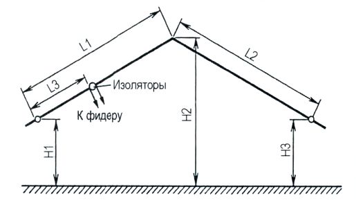
Graphic 1
But, regardless of how it is described, this antenna distinguishes itself by having an appreciable vertical component, without requiring a ground plane (counterpoise wires). To install the antenna only one mast is needed.
The lengths L1 and L2 of the radiator sections are 0,492λ, and the distance from the short end to the feed point (L3) is 0,139λ. Wherein, according to the calculations of the author, the impedance of the antenna will be about 50 ohms. The apex angle needs to be around 140 °. Mast height H2 should be approximately 0,18λ (which makes it somewhat less than the height of a GP antenna). The ends of the radiators (H1 and H3) must be at least 0.03λ above the ground.
Initially, the VP2E author tested on the 80 m band. That gave the lengths: L1 = L2 = 39 m; L3 = 11 m; N1 = NZ = 2,3 m; H2 = 15 m. based on a 2,5 mm antenna wire. With these dimensions, the input impedance at the required frequency of 3,78 MHz (corresponding to the minimum VSWR value) was 48 ohms + j2,8, which provided an SWR of not more than 1.1:1.
Note, that with this size, the antenna is able to be installed even on the top of a five-story apartment block.
Graphic 2 shows the results from the program ELNEC with three directional antennas in the same chart: VP2E, GP (quarter-wave vertical with four counterpoises) and a half-wave dipole mounted at a height of 15 m. The diagram indicates the direction, maximum radiation in the horizontal plane. As seen from this figure, the \/R2E and GP have a similar radiation pattern, but the VP2E has an angle of approximately 20 ° (which is close to optimum for the DX contacts) VP2E provides a signal level approximately 4 dB higher, than the GP and about 7 dB higher, than the dipole.
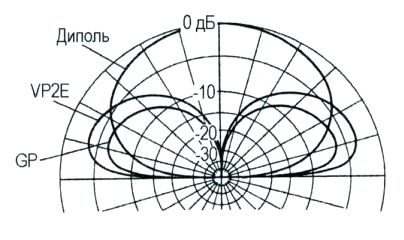 Graphic 2
At the 15m height, the maximum radiation pattern of the dipole looks to be almost vertical.
Unlike the GP, antenna the VP2E possesses some directivity in the horizontal plane, as does a dipole. Results of calculating radiation patterns in the horizontal plane for the three antennas are shown in Graphic 3. These diagrams were created for the directivity of the antennas radiation in the vertical plane at 20 °. The dipole and VP2E have similar radiation patterns and about the same ratio of the gain comparing the directions of maximum and minimum radiation (about 10 dB). In other words, looking at the VP2E, this measurement is not inferior to the dipole. However, the VP2E wins over the dipole by about 7 dB in the direction of maximum radiation. If looking for an “omnidirectional” antenna, naturally, the GP wins out with its circular pattern. But if you look at the directivity of the VP2E the lobe width in the maximum radiation direction is no less than 60 °. So while not “Omnidirectional” the “beam-width” is still quite wide.
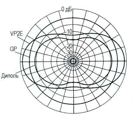 Graphic 3
A few words about the design of the antenna VP2E. Since this antenna has a noticeable vertical component, its supporting mast must be of an insulating material or have an insert in the metal decoupling the mast from the ground. Two decades have passed since the creation of the VP2E design. This antenna has been built by many Hams. There are reports on the Internet stating that “It works well” even with a metal mast if the mast is not grounded. Such results will require that the length of the mast is “non-resonant”. But in any case, a metal mast may slightly distort the antenna pattern and most importantly, “It works well “- is only a verbal assessment of radio amateurs. No one has carried out an objective measurement of the dielectric characteristics when a non-conductive mast is replaced by a metal mast.
Apparently, it is advisable, as in the case of many wire antennas, to add a “choke current balun” at the feed-point.
It is only natural, that the VP2E antenna can be constructed for other bands. Especially as it will be compact on the higher frequency ranges. As an example for the 20m band, the supporting mast only needs to be about 4m high. Such a construction can easily be mounted on almost any roof. Moreover, this antenna is very suitable for portable use when there are no suitable trees to hold a dipole antenna such as in open fields or on a mountain. While the mast is best made of a non-conductive material such as fibreglass this also makes for a light load to be transported to the portable site.
Interesting experiments have taken place with different antennas (including the VP2E), in which the mast is used as part of the antenna. The results of these experiments can be found in the article “Portable HF antenna for mountain expeditions” by UA6HJQ at web address http://goryham.qrz.ru/ant/udo4ka.htm#5. Since the commonly used masts for portable operations have a length of 4 to 7m, these are suitable for a VP2E antenna on bands 7 MHz and higher. For reliable operation of the antenna mast please refer to the website of UA6HJQ.
His version of the VP2E antenna has been designed to run on the 20 m band. The mast has a height H2 = 4,2 m, and the length of the radiator – H1 = H2 = 10,4 m. The ends of the radiators have to be raised above the ground by H1 = H3 = 0,6 m. UA6HJQ checked this value using the well-known program MMANA (the configuration file used for this calculation is in the aforementioned article on his website). He found out, that the feed-point in his version of the antenna needed to move somewhat (L3 = 6,3 m). This is not surprising. The right side of the radiator (see Graphic 1) – is effectively a half-wave dipole with an off-centre placed feed-point, and the offset can be made in any direction from the centre. According to the author, his version has a changed radiation pattern in the horizontal plane – the antenna has become more “circular”.
The SWR of his antenna was 1,5 at 14 MHz, 1,1 – at 14,1 MHz and 1,7 – at 14,3 MHz. In other words, it was quite acceptable over the entire 20m band.
The VP2E antenna has been known of for 30 years. It’s natural therefore that sooner or later, radio amateurs will have the idea to make it into a multi-band antenna. Any multi-band antenna is a compromise. Even those antennas, that manage to realize an acceptable SWR on multiple ranges (without a separate ATU matching device), create different radiation patterns on different bands. On one band you may have maximum radiation while on the others you have poor radiation. With the VP2E nothing can be done. Radio Amateurs often have to put up with compromises in their antennas but in this case, a specific antenna needs to be built to fit the requirements of a specific band.
If no other antenna is available, the VP2E can be “matched” to several amateur bands and will operate like a “random wire” antenna. The VP2E is particularly good for portable operation and its’ feed coax should be kept to 10 metres or less. When used not on its primary band using an ATU high SWR ratios should be expected.
Of course, when on some bands the VSWR is not very far from 1:1 an antenna can operate on them without any additional matching device. An interesting idea to provide the capability of a second band to the VP2E antenna was suggested by Ukrainian Ham UR0GT. On the 40 meter band, he has his 20m VP2E working as an INVERTED V off-centre fed dipole and setting it on this band actually has the correct total emitter length. His adjustments for 40m have not affected the operation of the VP2E on 20m. He has managed this by adding a freely dangling wire of about 1 m in length at the point of inflexion. By varying this wire’s length, You can shift the operating frequency across the 40 meters band. This additional wire has no effect on the 20m antenna because at this frequency it is located in an antinode of the antenna current.
Other experiments with a similar RW6AVK antenna are documented at http://www.lan23.ru/misc/VP2E_2b/2bVP2E.html .
Calculator.
Click vp2e-calculator to download my Excel calculator to insert your own frequencies.
 Enter your required frequency in the yellow field to recalculate the other fields.
FIELD TESTS: Initial tests 17th. January 2019
Once the snow had started to melt and before the next storm front arrived, I managed to set up the antenna temporarily in my garden. The centre was supported by the flag pole and the ends were tied off to two trees. Hardly an ideal setup but good enough to test. I have deliberately cut the wires long and my first check had the antenna resonant at 13.395MHz after first folding back and then cutting off about 6” from the longer length of wire and 3” from the shorter one, I got the resonance to be around 14.285 MHz as I wish to operate SSB QRP with this antenna. That said at this setting the antenna is less than 2:1 across the whole band. I also tested using a WSPRLite unit running 200mW. I was quite happy with the results:

At the bottom of SC 24, consistently getting into the US south-east, Ireland, Iceland and also Greece is a good result. The antenna was running roughly NNW-SSE unfortunately I don’t have enough room to be able to turn the antenna around to check its directive abilities. That will have to wait until I can get it onto a large open SOTA summit.
Here are some pictures of the set-up: 
FIELD TESTS: Directional Testing – Friday 1st. February 2019.
Well, I finally decided to give up trying to find a wide-open space in the country to test out my new antenna. The amount of ice and snow around means that the places I would like to use are simply not accessible.
I decided to test to see if there was ANY directivity from the antenna at all in my garden. With limited space and buildings all around this was never going to be a conclusive test and bad propagation conditions also meant the number of stations receiving my 200mW signal from a WSPRLite transmitter was going to be at a low signal level as well.
Rather than hope for a better location and better conditions, however, I decided to go with what I have. So using the convenient flagpole I raised the centre of the antenna up and then ran the long side (i.e. the side without the feed-point in it) across our common car parking and garage access area, fastening off the cord on the fence on the other side and then hanging a yellow cloth on the spot where someone coming out of the houses might walk into. Luckily no one came out or went in during the tests as, as well as possibly de-tuning the antenna there may have been some time taken up while I had to explain what I was doing and why.
The other side of the antenna sloped down from the flagpole almost (but not quite) in line with the first side of the antenna, under (but not touching) my tilted-over VHF steel mast and the cord tied off to the fence.
This positioned the antenna wire roughly from West to East, with the feed-point on the eastern side, meaning the antenna supposedly will have some gain to the west.
I now connected up the WSPRLite unit, synchronised its start against an atomic clock App and let it run for about 10 minutes before stopping it and then moving the ends of the antenna around. The end that had been across the car park pointing to the west moved into the garden and ran out to a tree in a northerly direction. The eastern end of the antenna now should move to the south. Unfortunately, there is not enough space in the garden to fit this in and the compromise was that it ran SSE rather than due south and then the end of the wire hung down in the tree after going over a branch. This was the side of the antenna with the feed point in it, so the antenna should now have some gain in a “sort of” northerly direction. After the 10-minute break to move the ends of the antenna, I ran the WSPRLite for about 10 minutes again.
Here are the results from the WSPRnet site:
| Timestamp | Call | MHz | SNR | Drift | Grid | Pwr | Reporter | RGrid | km | az |
|---|---|---|---|---|---|---|---|---|---|---|
| 2019-02-01 11:14 | DD5LP | 14.097123 | -16 | 2 | JN58la | 0.2 | R3TJP | LO16wg | 2397 | 55 |
| 2019-02-01 11:14 | DD5LP | 14.097090 | -15 | 3 | JN58la | 0.2 | TF1A | HP94lc | 2622 | 325 |
| 2019-02-01 11:08 | DD5LP | 14.097090 | -8 | 1 | JN58la | 0.2 | TF1VHF | HP84wl | 2688 | 325 |
| 2019-02-01 11:06 | DD5LP | 14.097090 | -12 | 1 | JN58la | 0.2 | TF1VHF | HP84wl | 2688 | 325 |
| 2019-02-01 11:06 | DD5LP | 14.097094 | -20 | 0 | JN58la | 0.2 | EA8BFK | IL38bo | 3033 | 234 |
| 2019-02-01 11:06 | DD5LP | 14.097090 | -13 | 0 | JN58la | 0.2 | TF1A | HP94lc | 2622 | 325 |
| 2019-02-01 10:54 | DD5LP | 14.097090 | -12 | 2 | JN58la | 0.2 | TF1A | HP94lc | 2622 | 325 |
| 2019-02-01 10:54 | DD5LP | 14.097090 | -15 | 2 | JN58la | 0.2 | TF1VHF | HP84wl | 2688 | 325 |
| 2019-02-01 10:50 | DD5LP | 14.097090 | -20 | 1 | JN58la | 0.2 | TF1A | HP94lc | 2622 | 325 |
| 2019-02-01 10:44 | DD5LP | 14.097091 | -25 | -1 | JN58la | 0.2 | TF1A | HP94lc | 2622 | 325 |
| 2019-02-01 10:44 | DD5LP | 14.097090 | -18 | -1 | JN58la | 0.2 | TF1VHF | HP84wl | 2688 | 325 |
As the data is in reverse sequence, the top six entries are from when the antenna was “beamed” ‘sort of’ north and the bottom five entries from when it was “beamed” west.
Luckily we have reports from Iceland in both batches so we can compare those.
Averaging the readings into TF while the antenna was “pointing” west we get an average signal of -18dB comparing this to the average of the signals when the antenna was “pointing” NNW-ish which was -12dB gives us a difference between the end-on direction and the side-on direction of 6dB. That is more than expected and could be caused by Iceland being in one of the side nulls of the antenna pattern or (more likely) by the various obstructions around the antenna.
These results suggest the antenna is directional to an extent but the results are not conclusive and a test in a truly unobstructed location is really needed. It is also possible that in the 10 minutes taken to “rotate” the antenna, band conditions could have changed.
While packing away the antenna, I measured the short and long sections of the antenna as previously trimmed to give resonance on 14.285MHz using an antenna analyser and the short section is 6.32m long as compared to the calculated 6.30m and the long section is 14.75m long as compared to the calculated 14.48m – so fairly close. The actual length is affected by the velocity factor of the wire used, however, I am fairly confident that should an antenna be cut exactly to the settings found using the calculator, it would indeed be “close enough” to work.
Bill of Materials
– parts from Sotabems.co.uk (parts for one band 10m – 80m)
- Thin light antenna wire (100m reel) Price € 9.22 (Hi-Viz yellow recommended).
- Centre wire support for the top of the mast Price €2.18 (5 pack)
- “invisible hardware” (Feed-point T + 2 x end insulators) Price €3.26.
- Coax feed-line (10m RG-174A no plugs fitted) Price €8.88 (add required BNC or PL259 plug yourself (a BNC plug costs €2.18 from SOTABeams)).
- Guying pegs (metal) Pack of 3 Price €1.68
- Cord (Hi-Viz recommended) Price €9.50 for 50m (need < 10m).
TOTAL COST OF COMPONENTS: € 36.90.
OR …… Simply buy the Linked Dipole kit at €17.04 and add the mast top insulator (nr. 2 above) €2.18, antenna wire (nr. 1 above) €9.50, feed line coax (nr.4 above) €8.88, and a BNC plug €2.18. Total cost € 39.78 where you get two winders to keep the antenna tidy and if you want to try to make a multi-band version you already have the link pieces and crocodile clips.
You will need to supply your own mast or buy the appropriately sized one from SOTABeams (Tactical, Tactical-Mini or Mini-Mast). Or hold up with a rope over a tree branch connected to the centre wire support.
Multi-band decision.
While waiting for the weather to improve I wondered if a linked version of the antenna would be practical. In a similar way to how you can have a linked dipole.
My first linked VP2E was one for 17 & 20m which with the links inserted it was to operate on 20 metres and with no links it was to operate on 17 metres.
I then took my original 20m VP2E and extended it for 40 metres usage. Initial testing and experimentation with these antennas suggested they “should” work “OK” but after a few activations, I found that the compromises were not good. The difference in height required and the positioning of the feed-point for the band being operated on meant that (especially on the 20/40m model) when one band was correct with a reasonable SWR (up to 1.7/1.8:1) the other band was over 2.2:1 and the antenna was no longer resonant within the band.
While it MIGHT be possible to “dual-band” this antenna for bands that are close together (10-12m, 17-20m etc) it is NOT a good idea to try to create a 20m/40m version.
MY RECOMMENDATION IS TO USE THE VP2E AS A SINGLE BAND ANTENNA.
FIELD TESTS: Further directional testing (40/20m linked VP2E) 25/4/2019.
While working portable from GMA “summit” DA/AV-077 Kramerberg / Beaches on the Air BOTA 19685 Windachspiecher I did some more directivity testing as I had a wide-open space with relatively few obstructions.
I performed the tests by using my WSPRLite unit and “pointing” the antenna in three directions (WSW, NNW & WNW). As the WSPR system is a slow beaconing system, there is the danger that the results may be incomplete or affected by propagation changes on the 20-metre band which I used. Of the results gathered I only took the values from stations that received my 200mW signal in more than one antenna direction and compared the SNR values to see if any ascertainable “gain” can be found. This amount of data will not enable a radiation pattern diagram to be produced rather it can only indicate that the antenna has nulls and is not uni-directional. Had I known which WSPR receiver stations were going to be able to receive me I may have targeted one or two and adjusted the antenna direction for maximum SNR at that station and hence found the “beam-width” of the antenna. Perhaps another time.
For now, here are the filtered results from multiple reception reports with the antenna in different directions from a few stations:
 The relative directional gain figure is based on the lowest signal received by the station – setting that as zero and then with the antenna in different directions noting how much stronger (less dB under the noise level) the signals are.
The only conclusion from this test is that the antenna does have nulls and peaks in its pattern of between 3 and 6 dB and is NOT equally omnidirectional.
As luck would have it, in no situation did I actually have the antenna exactly “pointed at” the receiving station, which would have enabled me to confirm that the antenna radiates more off the “front” side (the side without the coax-feed) than elsewhere (or possibly front and back radiation are about the same but there are definite side nulls). It looks like DK8FT is a semi-permanent WSPR receiving station and being not so far away is less likely to be affected by propagation, so another test “targeting” (i.e. only looking at the readings from) this station would be a good option.
Until then, we will need to continue to hope that the radiation pattern in the diagram below is somewhat accurate. The antenna certainly appeared to work well on my recent SOTA activations.
Antenna simulation using MMANA-GAL from ON8IM:
(modelling file at:https://www.on8im.be/images/mmana/V2PP.maa)

 Further “improvements” to the VP2E antenna.


I decided to try adding a BALUN to my 20m VP2E antennas to see if that helped the matching and hence VSWR back to the rig. Did it work? Simple answer – No, using the balun made no difference. While it may reduce the amount of RF coming back down the coax sheath, I’m not running enough power to be worried about that.
Adding matching components at the T-piece feed-point.
After almost 2 years of doing little on the VP2E, I tried an activation with the 20m version and my current rig – a Xiegu G90. The G90 has an internal ATU in it and when trying to match the VP2E on a summit, it seemed to take longer than I had expected, so I decided to put the antenna onto the analyser when I got home.
This is what I found:
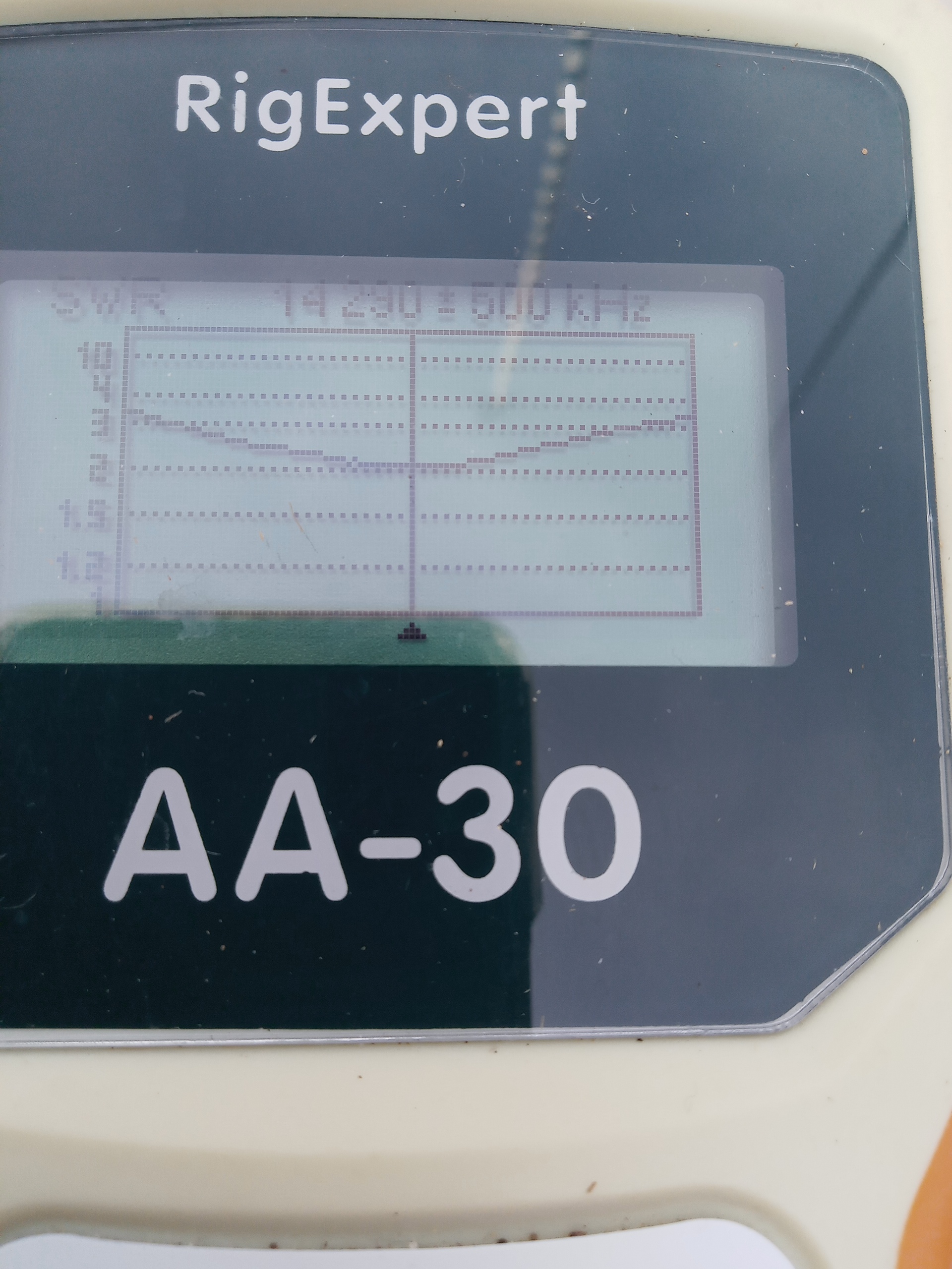

As we can see, the antenna is resonant around 14.285/290 which is fine however the SWR is around 2:1. With the next screen, we can see the reason – R is 33 ohm and X is -28 ohm. To address this problem, I decided to create a matching circuit calculating the required components with the online RF Impedance Matching Calculator as shown below:
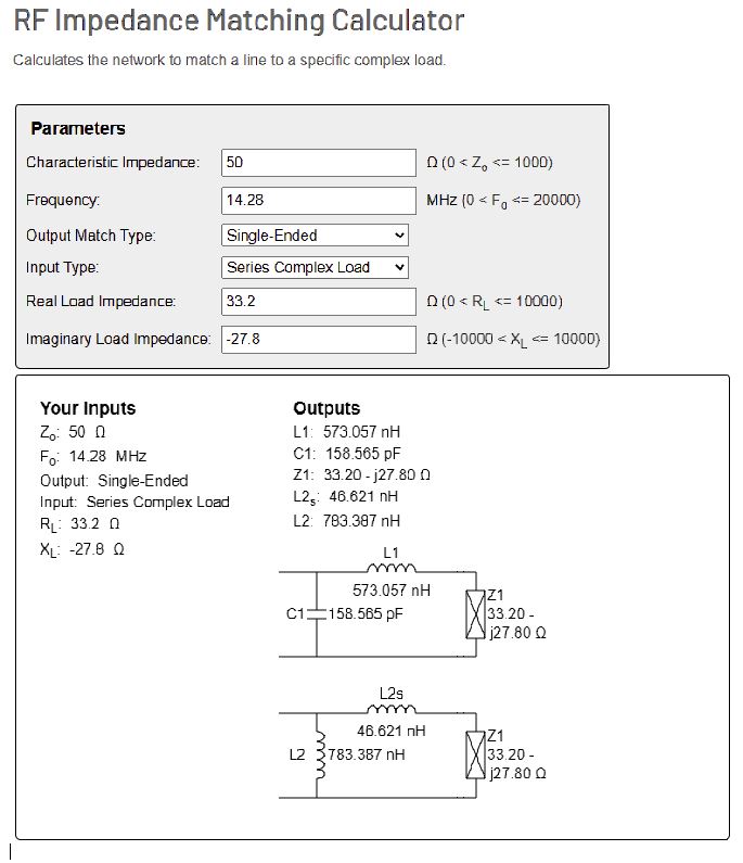 I took the first option and added the inductance and capacitor to the feed point on the antenna.
The result ….
 The SWR is now UP to 3:1 and the values …
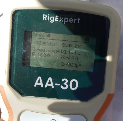 R is now 18 ohms and X -2.3 Ohms!
While X is getting closer to the wished-for zero, R is getting worse.
Conclusion – This was not a good idea – put up with the 2:1 SWR without a matching circuit!
More testing is needed in an open area and ideally with a second person to assist. This antenna may be critical regarding mast height and the resulting angles of the wires.

You must be logged in to post a comment.