
### Warning – this article is going to read like a diary or log of actions with some changes needed along the way – that is how I have written this, I hope you can condense out of it the parts you need to go and build your own PVM (Portable-Vertical-Moxon). ####
With Solar Cycle 25 slowly improving radio conditions on the HF bands, I wanted to build an antenna for portable use on the 10 metre band. I have the Komunica HF-PRO2-PLUS-T of course and the OCF dipole will work on 10 metres but as we are talking smaller dimensions on 10m when compared to 20 and 40m, I would like to have an antenna with some gain and directional advantages. I already have commercial (Par Electronics) Moxon antennas for 6 and 2 metres and know that the design is good in two ways, that it is solid and that it works at least as good as a 2 element yagi, often better. I have already built a wire Moxon antenna for 15 metres on the wooden floor of the loft over the garage – with it pointed permanently towards the US. This sort of worked but was limited by the items around it and of course, being pinned to the wooden floor, it couldn’t be turned.
So I started thinking about how, in a true backpack-portable configuration, I could make a Moxon beam for the 10 metre band. At first, I was considering what I could use as “spreaders” to hold the wire elements out where they should be and then once I had it assembled, to hold it, I would need something more permanent than my usual telescopic fibreglass fishing poles – so probably an aluminium mast and a guy ring so that it could be turned around. Perhaps the mast could stay fixed and if I use the 6-way water pipe junction that I bought out of China to make a Moxon for 17m for the home mast (but never got around to it) as the centrepiece for the spreaders this could perhaps turn around on my portable aluminium (caravan TV) mast?
I then stopped and considered the practicality of this, while probably a very stable, but also complex arrangement it would not be easy to put up on a summit or even in a park. In fact, when activating alone (as I normally do) – it would be too complex – not to mention too heavy to carry.
Another solution was needed. I got to start thinking about – what if I put the Moxon in a vertical polarisation rather than a horizontal one? While this would not be good on 6 metres or 2 metres as too much signal would be lost as everyone else would be horizontally polarised, on the HF bands, with signals twisting as they reflect off the Ionosphere and with the fact that on 10m SSB there’s a mixture of stations using vertical or horizontal polarisation in any case, building a vertically polarised Moxon could be a practical solution.
I’d still need a relatively strong mast to hold the cross booms so that the MOXON would be like a square sail on an old sailing ship and turning the mast would change the direction of reception and transmission. Now, while there are some very good designs to do exactly this, it still needs a solid mast and two cross booms to be carried to the summit and probably with the weight of the cross booms, a good guying solution.
Back to the drawing board – what are my requirements?
- Moxon antenna with a few dB of directional gain – ideally made from wire.
- Lightweight so that it can be carried to a summit.
- Small so it can be packed in a 40 litre (medium-sized) rucksack.
- Capable of handling 20w or RF.
- Rotatable.
- Initially, for a single-band – 10 metres but possibly later able to be adapted or parts of it re-used to create 12 and 15m versions on the fly.
After some thought, what I came up with, by looking at what I already had and considering the fact that fibreglass (not carbon fibre) masts do not affect an antenna, so the wire can run along them – was to run the antenna wire up two telescopic fibreglass masts and by their positioning, pull two inter-connecting wire runs taught between them, so as to form the required rectangle for the Moxon design. So as not to fire the radio signal straight up or straight down, the feed-point for the driven element would be halfway up one of the masts and the horizontal wires between the masts would have the insulators in them, which breaks the rectangle into the driven and reflector elements of the beam. The second mast would carry the reflector wire with no feed-point break needed.
To get the dimensions for the lengths of wire needed, I used the same online calculator that I had used when I built the wire Moxon in the garage loft. It is located on the web here:
http://tippete.net/cgi-bin/moxgen.pl
Here are my scribbled notes of what I wanted to build:
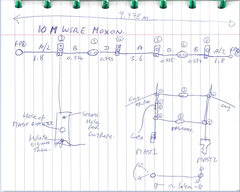
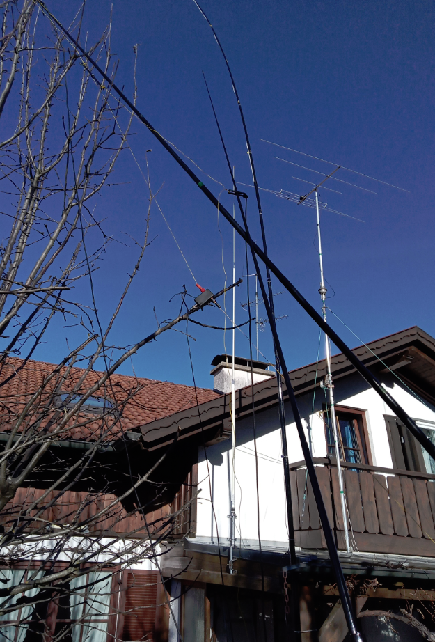
The basic plan was that mast number 1 (a 6-metre telescopic “GFK” portable mast from lambdahalbe.de ) will be fastened to a convenient fence post or something similar at the portable site and that mast number 2 – an identical 6m tall mast, will have a support foot of some kind as well as a guy rope made of sailing “snatch cord”. Mast number 2 would be positioned to make the antenna wires taut and also define the direction of reception and transmission. With this “steering mast” no mast rotation is needed, to change transmission direction we move the reflector element.
Towards the bottom of each mast, there is a small piece of PTFE kitchen cutting board material drilled to drop over the mast and with another smaller hole where the antenna wire goes through. More accurately drilled for the tops of the masts there are modified antenna wire spacers that drop down the mast to about the 4.5-metre level where the mast is less springy. These have two holes in each of them as part of their original spacer function and one of these is used for the wire to pass through while on mast number 2, the other hole is used for the guy rope. In some environments mast number 1 might also have to have a guy rope attached here.
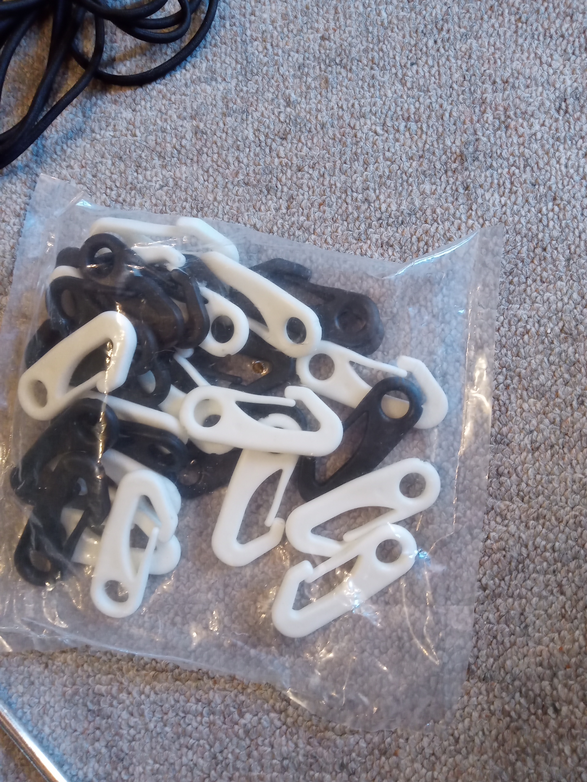
I said that the wire “runs through” these holes, that’s not completely true. The wire passes through these holes but is tied off at the correct length to form the correctly shaped and proportioned rectangle. My plan is to add plastic karabiner clips onto the wire to clip into these mast wire supports later so that I can swap out pre-made antennas for 12m, 15m or even 17m.
I had also intended to use a DX-wire T-piece to build the feed-point but this is doing good service in my SOTA linked dipole supporting a 1:1 balun. I remembered however that I had bought and built a Balun kit some years ago and never used it. That was brought into service for this antenna. This is a “proper” transformer Balun however at QRP, it ought to be possible to use this antenna without a Balun just having a T-Piece connection from the wire to the coax cable as this is a resonant antenna.
Set-up, testing and trimming of the prototype:
More tests to create a self-supporting solution – 1/1/2022.
The next challenge was to make this solution free-standing, so that should there be no fence post on a summit I can still use the antenna. I eventually got time to get out into the back garden again to try out my new mast stakes – perhaps I should call them “Miss-stakes”… Actually they’re ingenious things, meant to support thin fishing rods.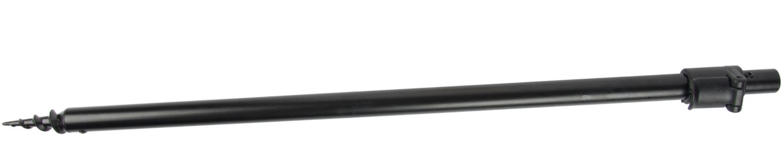
They have a screw-in point and then about a metre of Ali-tubing and a clamped inner section that comes out to add over another half a metre and the very top has a threaded cap where presumably some fitting on a rod fits into.
In any case, rather than strapping my fibreglass telescopic travel masts to the side of these, I decided to simply unscrew the bottom plug on the mast to allow me to sit the mast over the outside of these poles. Sounded good except, the clamping lever is so large that the mast will not slide over it and hence the bottom of the mast sits at about a metre off the ground. These little poles are relatively stable and getting a little more height might not be a bad thing or…
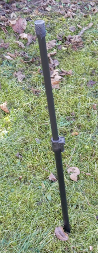
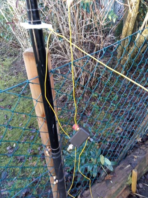
I started to put the antenna up – yes the bundle of wires in the picture below is an antenna …
When I plugged the coax into the balun and raised up both masts, all fine, until … I tried to move the second mast out to take the slack out of the horizontal wire runs – a similar action to what I will need to do to “steer” the beam and this happened:
The primary mast collapsed into itself and then fell over.
Given that even if a fence post is used to support mast number one, the solution needs to be stable enough to move mast number two while fully extended, to steer the antenna, without the antenna collapsing.
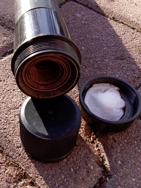
So the new plan is to saw off the clamp piece in the base poles (where the masts are sitting on at the moment) and remove the inner extension pole so that the fibreglass masts sits on the ground with the nearly 1 metre of aluminium support post inside them. This ought to give a little more stability. I might also add a rope across the bottom of the masts so that the spacing is a known distance.
Ensuring the bottom of the mast sits on the ground, avoids another problem which I hit – that my guy ropes were no longer long enough!
Modified support posts
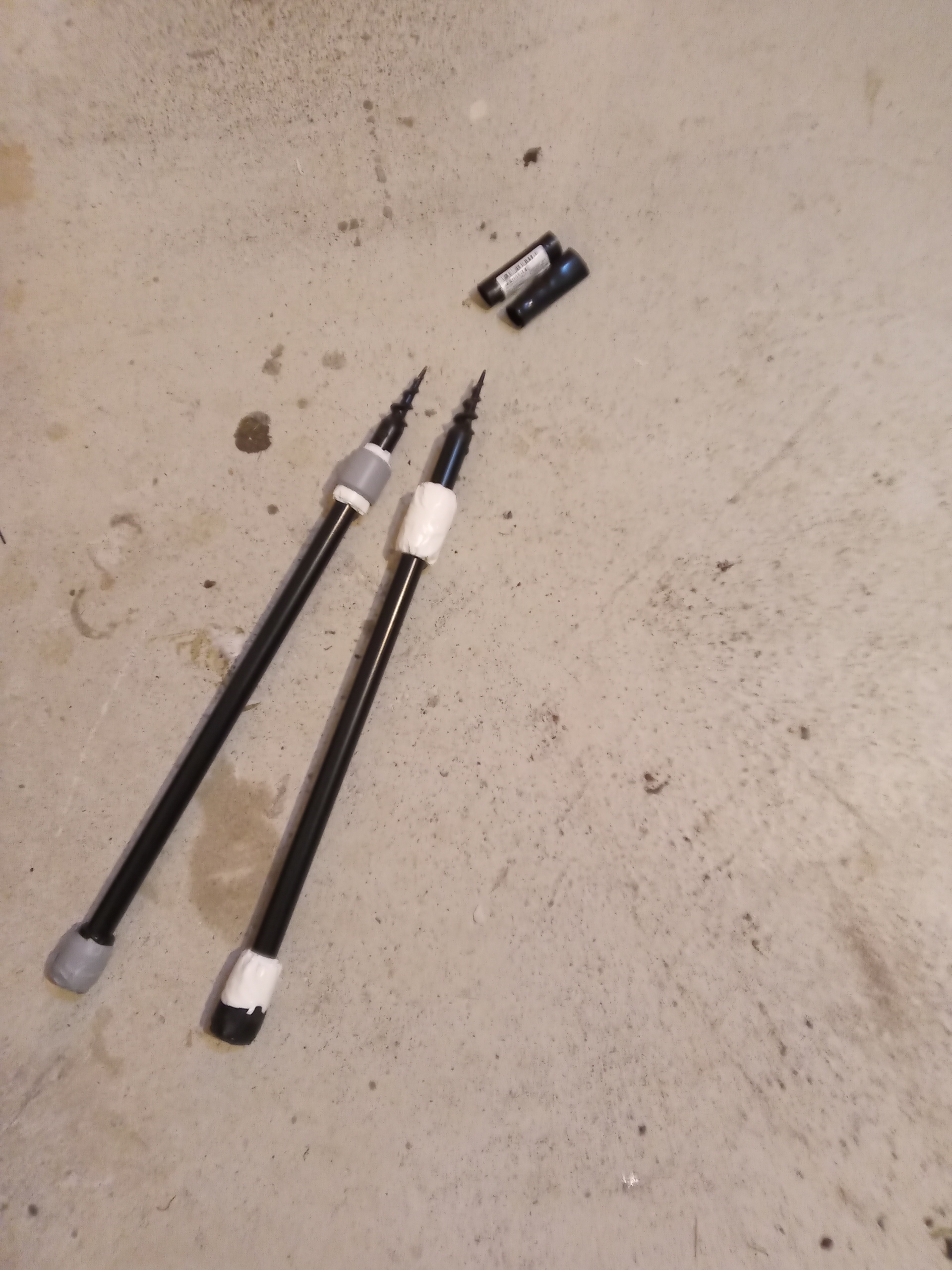
The inner telescopic rod and the locking latch lever have been removed so that the outside section of the telescopic fibreglass mast can sit at ground level. The width of the posts were increased with tape at the top and bottom of the poles so that the mast sits firmly on the post.
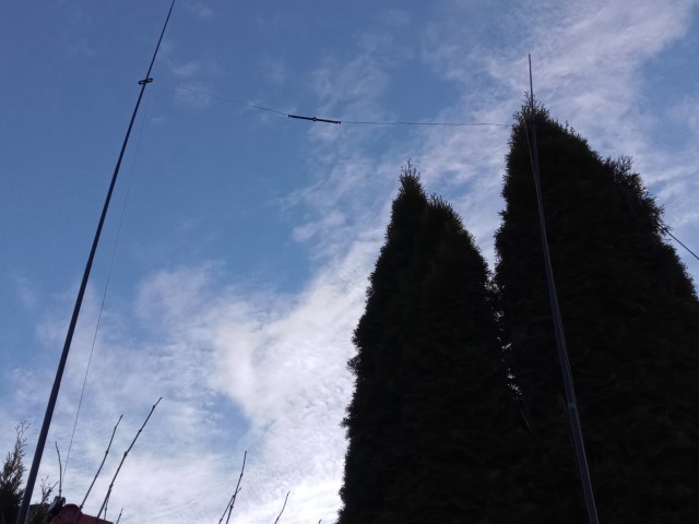
Trying out the modified support parts (no antenna attached):
I had limited time and I would have liked to have done another full test in the garden, perhaps even attaching a radio to the antenna however I decided to concentrate on testing that the updated supports now hold the 6m travel masts better than they did.
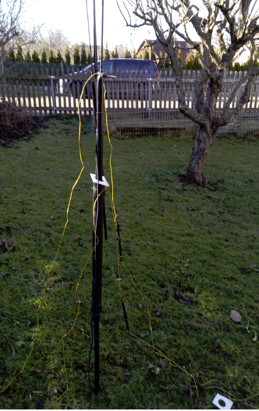
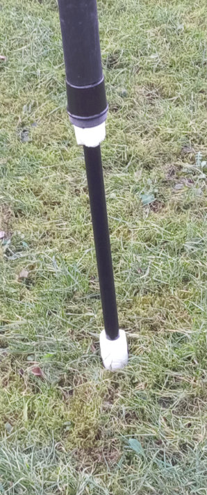
This first photo shows how the fibreglass, telescopic mast slides over the support rod to sit on the ground:
Here are both masts on the support rods, with the measuring rope between them to make sure they stay the correct distance apart when I move the mast holding the reflector to change the beam direction.
![]()
End-of-test – result – yes the masts are held a lot better when their bases are on the ground rather than sitting on the clamping mechanism that was previously on the support rods.
… So now I need to wait for some more reasonable weather to do a full test.
But before I got that opportunity, the Karabiner clips arrived and I remade the antenna using these so that the antenna will pack away easier and in fact, I can even just create different sets of wires now to use the same other parts (mast rings, guy ropes, Balun etc.) for 12, 15 and 17m versions on the antenna.
Full test on the now completely able to be disassembled antenna – 15/02/2022.
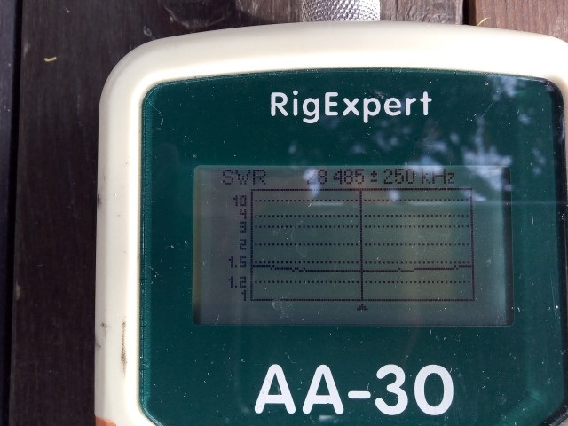
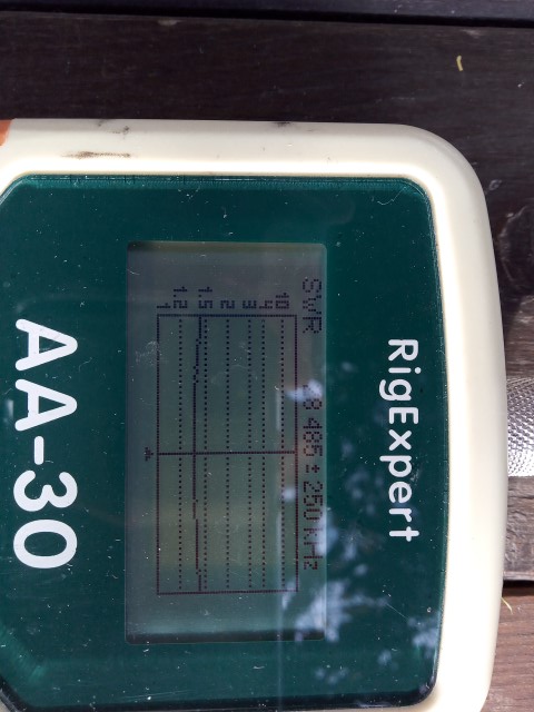
A successful test of the Moxon, including moving it to “beam” in other directions and using the new clips to make the set-up and take-down easier. One surprising finding was how wide a frequency it covers – right from 27.5 through to 29.7MHz at an SWR of 1.7:1 or less.
The band was closed but I could hear the local (35 km away) beacon fairly well, in fact, I tried to use it to measure the directivity of the antenna and at first, I thought it looked good but then I realised that the beacon transmits a sequence of different power levels so this test was inconclusive. I put out a couple of CQs on 28.5MHz with no replies. It would have been nice to get an actual contact but this also proved the portable Xiegu G90 rig was fine with the antenna.
I intend to add a second pair of snatch cord guy ropes so that the masts should be even more stable and I need to make a new “spacer rope” as the masts need to be a little further apart but apart from that, the antenna is ready for use from a summit.

You must be logged in to post a comment.