
Amateur radio Tripod Technical definition
Overview
1. Project Background and Description
In order to use HF vertical antennas which are normally expected to be mounted on a vehicle either with a boot-lip or magnetic mount and have a PL-259 plug at their base, some form of support is required when the antenna is to be used away from the vehicle – i.e. in a portable location in a park, on a summit, on a beach or even on an apartment or hotel balcony.
To this end I have adopted the use of a modified photographic tripod normally used to support a camera.
2. Project Scope
The Solution should provide the technical capability to use such a mobile vertical antenna in a portable location.
3. High-Level Requirements
The solution requirements are defined as follows:
- Lightweight and small to enable easy carrying to the location where it will be used.
- SO-239 socket to mate with the PL-259 plug on the bottom of the HF vertical antenna.
- Some form of “false ground” to simulate the metal car roof or bodywork that the antenna is expecting and which forms the other half of the antenna when in operation.
- Connectivity via a 50 Ohm co-axial lead from the mount to the radio.
4. Deliverables
A list of the individual components required, with example sources to be able to build the tripod mount.
A description of the actions required to assemble the solution.
5. Required components list
It is assumed that the reader already has a vertical HF antenna with a PL-259 plug on its base.
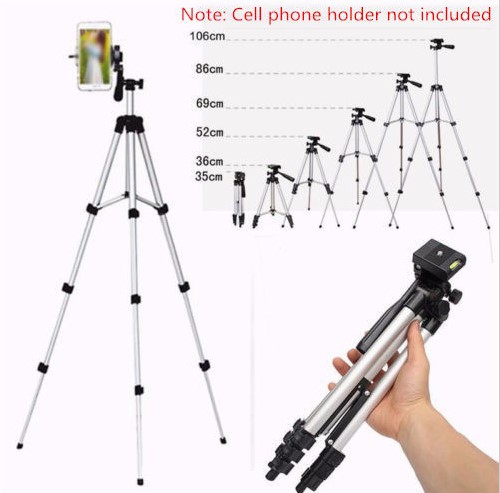
- The photo-tripod. Many different types of tripod can be used. Weight is the key issue however strength is also relevant so a compromise may need to be found especially for heavier antennas. When I built my unit, I used a tripod which I had already bought from the HAMA company – a well known company in the photographic world. This was the model: STAR 700 – EF Digital. This tripod even has a spirit level built in so that you can set the top of the tripod perfectly flat when on uneven ground. It also has nice quick release clips to set the leg lengths. I was surprised when searching eBay for an equivalent to find exactly this Tripod from a Chinese manufacturer for €8.97 which is a LOT less that I paid for mine – here is a link & picture:
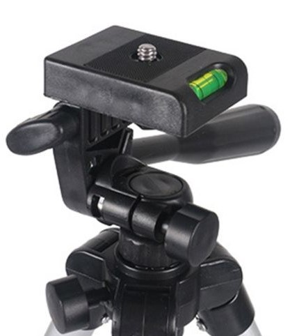
 You can of course use any other suitable tripod, based on what you already have or your particular wishes (e.g. stronger, higher etc.) the key point is to look at how accessible the top plate is as we need to add our SO-239 socket onto there:
- SO-239 socket and co-axial cable with PL259 plug.
In my original build I was lucky enough to find a SO-239 encased socket with a 50 Ω co-axial cable. You will need to search for the mounts which could look like this one:
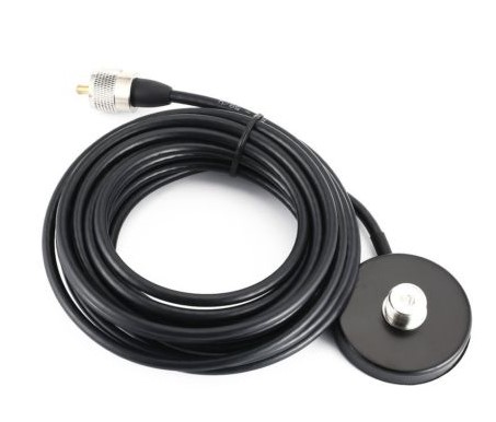
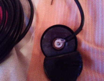
Except – this one is actually a complete magnetic mount rather than just the sealed SO239 socket which can be seen when the felt is pulled back – see the magnet around the outside of the SO239. This could be modified and the magnet removed but it would be easier if you can find a mount the same as shown in the “construction instructions” section below.
Of course, another mount can be substituted (perhaps a boot lip or similar mount – as long as you have space under the tripods top plate) but my instructions below are based on the use of this or a very similar “sealed” SO-239 socket with cable as often used as the top element on a magnetic antenna mount.
Radial wires – These are best made of “hook-up” wire in a bright colour, so they can be seen by you and others at your operating location. These can be cut to length or lengths for the frequency bands on which you wish to operate (for such an action you will need to use an Antenna Analyser, make the wires longer than a quarter wave on the band your require and then, with the main vertical antenna set to that band (if your vertical antenna is one that requires adjustment by band) trim back the radial wire or wires until you see resonance (indicated by a dip at the required frequency) on the analyser.
Alternatively, you can cut the radials deliberately to a length that is non-resonant on any of the bands that you wish to operate on. I took this approach and created my 4 radial wires with a length of 3 metres.
6. Construction instructions.
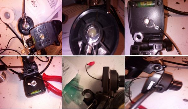
Once you have all of your parts available, the most complicated part is to add the SO-239 base to the top of the tripod, where the camera would normally screw on to. To do this ideally you would mount a nut of the standard camera thread into the base of the SO239 sealed socket however as the bottom of the base I chose is conductive silvered plastic, it is possible to simply create a thread into the plastic itself, using the bolt on the tripod plate, so that the SO239 unit fits easily on the top plate (see pictures below). I then added a cord with a clip to the bottom of the bolt that passes through the plate on the tripod.
 As stated above if you wish to use a different SO239 base, then you will need to find a way of fitting it to the top of your tripod.
My short fly lead on the earth side of the SO239 has an alligator clip into which I clip ends of my 4 (you may add more) radial wires (rather than just clipping onto the bared wires I soldered them all together and added another alligator clip to make attachment simpler).
If using 4 radial wires of the same length these should be laid out at 90 degrees to each other when the tripod is set-up. If you are using tuned radials of different lengths for different bands, experiments have shown that these can all be strapped together and therefore form a counterpoise wire which when positioned in the opposite direction to where radiation is wished for can make a slight difference in the radiation pattern. In general however the antenna will radiate uniformly around all 360 degrees.
7. Setup process
Once you have set-up the tripod and adjusted its legs to make sure the top plate is horizontal in both directions, attach the radial or counterpoise wires and run the coax back to your operating spot. Now assemble and attach your HF vertical antenna, taking care that there are no obstructions above the tripod, especially with the longer antennas. If the antenna needs to be tuned adjust the setting on the antenna for the band you wish to use.
NOTE1: the setting on the antenna tuning marks is unlikely to be the same position as it is when the antenna is mounted on a vehicle. An antenna analyser will allow you to create your own chart of rough settings per band as to where the setting needs to be for resonance on a particular frequency. UPDATE: I have found that by using 8 non-resonant 3 metre long radial wires, the readings on the tripod are much closer to those on the car roof (and hence those supplied with the antenna) than when only using 4. Going to 10 radials or perhaps 8 x 4 metre long ones could mean that the same settings may be possible for the antenna sat on the car roof or while on the tripod as a true portable antenna.
NOTE2: the radials or counterpoise are affected by the type of ground you are on, whether it is wet or dry, rocky or soil, so the chart of settings can only be a guide and some small adjustment on adjustable antennas will be needed on-site. This can be done by watching the SWR reading either from an inbuilt or external SWR bridge.
8. Restrictions
This solution is only intended to support HF antennas that are normally vehicle mounted NOT home station verticals that may have a PL-259 plug at their bottom.
Do not overload the tripod. If you feel your antenna is too heavy for the tripod I suggest above, then buy a stronger (and hence heavier) one and accept the compromise of the extra weight to be carried. SAFETY FIRST!
Ed Durrant DD5LP

You must be logged in to post a comment.