
The Scope of requirements:
A vertical antenna for use on a summit which needs limited space to deploy (ideally no counterpoise or groundplane wires) , is light to carry and small to pack-up. It should be able to handle the 25-30 watts of RF from my small amplifier.
 The history of the antenna:

I read a very interesting post on the Sotawatch reflector for a coax fed vertical which requires no Balun or ATU and no radials through the use of a quarter wave matching stub. The article thread is here:
http://reflector.sota.org.uk/t/efhw-dipole-mono-band-version/13984/1
References to background articles and a useful calculator can be found in this article.
After grabbing some RG-58 coax and running the required 20 metre frequency 14.285MHz through the calculator I built a version of this antenna for 20 metres, tried it connected to the 10m DX-wire “Mini-Mast” in my garden (which collapsed into itself during the test). The Antenna Analyser said it was on-frequency with a low VSWR, so I decided to take it out to Weichberg and give it a test. The weather was horrible – sleet and ice rain, so the activation was very short but I managed after several calls to make contact with a greek station and received a reasonable report. Shortly after the contact the DX-Wire pole collapsed into itself again and I decided to pack up and leve, noting the DX-Wire pole is a problem when it collapses with such little weight on it.
A few days after returning home, I decided to build a new version of the antenna, this time one for 15 metres as that wild then fit on my usual 6 metre high mast from LambdaHalbe and as I was now considering contacts into the US for the upcoming EU-NA S2S activity period and previously I had had success on 15 metres. I also decided to build the antenna with what I thought was RG-174 coax (the very thin and hence light, co-ax cable) the already fitted plug on the cable was marked 174, the cable itself had no markings. I could not get the new antenna to come to resonance. The Velocity factor, which is the main thing along with frequency that decides the length of the coax-cable in the antenna was the same as the RG-58 (0.66) or so I thought, then I looked round on the Internet to find that the RG-174 cable with foam insulation has a different velocity factor of 0.753 instead of the PVC version which has 0.66. I re-calculated the lengths and now built both a 15m and 20m version to see if either of these would come onto frequency. They didn’t. I then decided that the calculator may not work correctly for thin cable and as the resonant frequency of both of these antennas were 200 KHz higher than they should be, I put a frequency in 200 KHz lower than required to give what might then be the correct frequency and rebuilt just the 15 metre antenna. It was “close” so with a small adjustment to the insulated wire element part of the antenna,I managed to get a reasonable result. This antenna was then tested on Buchberg and I managed 4 contacts into North America on 15 metres with it using just 5 watts (the amplifier had blown one of its transistors on Weichberg without me realising until I saw it was not operating on Buchberg). So a success with the coax fed half wave vertical antenna which was now being called a J-Pole.
After returning home, and repairing the amplifier, I was still not happy with the hit and miss measurement of the antenna and as it looked like most activators in the upcoming EU-NA S2S event on the 19th. of November were going to be on 20m not 15m, I had to build versions for 20 metres and 17 metes as well, to be sure to be able to get onto the bands where the others are and where propagation is working. It was at this point that I spotted some more of this plugs attached thin grey coax cable in my old projects and they were in use as Q-sections on a couple of portable full wavelength loop antennas – the penny dropped – this cable is NOT RG-174 despite what is marked on the plugs, it’s actually 75 ohm RG-179 co-ax which has a different velocity factor again of 0.70! No wonder the calculator couldn’t give the correct lengths!
I searched around for some real RG-174 and having none in the workshop supplies, I ordered a reel off eBay which arrived a few days later. As this was purely a reel of cable, I thought I would retain at least the feed out of the T connection to the rig in the antennas on the RG-179 coax as that would not affect the length of the (now real RG-176 0.66 VF co-ax) antenna coax lengths. With this set-up although the resonant frequency of the three antennas were closer, the 75 ohm impedance meant the VSWR was near to 2:1 which while workable wasn’t ideal, so I then replaced these leads also with 50 ohm (RG-58) pre-plugged short cables.
These versions of the three antennas were much better and only needed adjustments to the insulated wire element length for which I use very thin (and hence light) 24AWG printed circuit board track repairing wire, rather than the expectd by the calculator “hook-up” wire.
 The complete solution:
So now I have sorted out why my lengths were not as expected (I was using RG-179 coax not RG-174 as I had thought) I have built three J-Poles antennas that are resonant on 15, 17 & 20 metres …. “but wait there’s more”.
Following some very annoying occurrences of the DX-Wire 10m mini-mast collapsing on me and it being heavy to carry, I updated my “Scope of requirements” to include using the 6 metre Lambdahalbe mast not the DX-Wire one (the 6m mast is less than half the weight of the 10m mast and shorter to carry). By winding the wire around the mast, it is possible to fit either the 15m or 17m antennas onto the mast. The 20m J-Pole insulated wire element however is too long to fit on the mast. In all three antennas I built the coax feed and stub / T-junction separate from the wire element and have 2mm gold plated RC battery connectors in between to connect them. This was initially done to make packing and assembly / disassembly easier as I can simply coil the coax part and the wire part winds onto a small former.
What to do about the 20m antenna? Perhaps I can run off the excess length from the top of the mast, Inverted-L like and guy it down on a thin cord at a distance? This would be one solution but another idea struck me – why not simply run the excess out at the bottom of the mast at about 1.5 metres high, over onto a walking pole or similar?
This antennas design is single band. the coax assembly is different for each band as is the insulated wire element, however I then looked at what I was thinking of doing for 20 metres and thought well I can do that for 17 metres as well and then just leave the 15m element on the mast and plug in extra lengths of wire element for the other two bands when needed. The major advantage of this approach is that I don’t have to take down the mast, coil-up the antenna and then put the mast up again with a different wire element, every time I want to change bands. Switching the coax assembly for each band is simple as I have theses as separate modules in any case.
The question was, would this 15m plus 17m or 20m extension actually work in practice – electrically apart from the extra connector it should look the same.
I tried this solution and here are the resulting readings from my antenna analyser (sorry for the reflections):
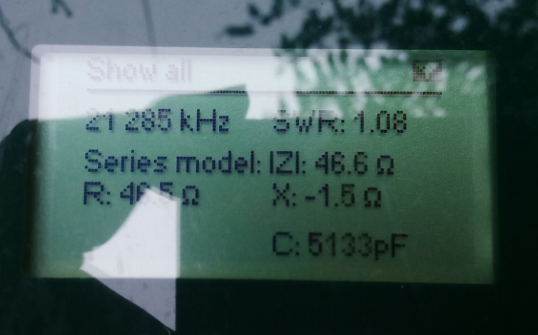
15 metres – 21.285MHz 1.08:1 SWR

17 metres – 18.010 MHz 1.09:1 SWR (picture taken before a small adjustment on length to bring resonance to 18.130MHz)

20 metres – 14.285 MHz 1.15:1 SWR
So you can see, it appears to work and … I have reduced the weight in the process,
Parts now to be packed –
Core items (total weight 213 grams):
3 RG-174 coax assemblies with short feed cable
1 half wave 21MHz insulated 24AWG element
1 short 24 AWG extension for 18MHz
1 short 24 AWG extension for 14 MHz
Plus: 1 extension BNC-BNC cable to connect from short link on antenna to rig or amplifier and of course the LambdaHalbe 6m portable fibreglass mast.
This is the configuration I plan to use for the EU-NA S2S event – lets see how these work on a summit!
Updated version – March 2017.
The antenna worked well in the EU-NA event but I still wanted to amke it simpler to deploy, so here is the updated version.
THREE antennas (15, 17 & 20m) with their LambdaHalbe 6 metre lightweight pole:
These three HF end fed half wave dipoles with quarter wave matching stubs need no radials or counterpoise. I built them small and sooooo light (albeit with the wire I use (PCB board patching wire) any more than about 30 watts into them and they could glow!).
The way I work this combined set-up for three bands is; I use the cheap and ever so reliable LambdaHalbe 6 metre pole. The 15m half wave is spiralled down around the pole and sits nicely at the top of the second section (about 1.5m off the ground). There I have a small 2mm RC gold plated DC connector onto which I attach the coax assembly that is cut for the 15m. band – the other end of that goes to the output of the amp or directly to the FT-817. The analyser shows a beautiful wide bandwidth – anywhere in the band is below 2:1 most below 1.5:1.
For 17 metres, the cable coming down the mast stays the same but I then plug an extension wire (now wound on a plastic former) and then the output of that (still using those 2mm RC connectors) goes to the coax assembly for 17 metres and on to the amp/rig.
For 20 metres, same procedure as 17 metres except using a different former with the 20m extension on it and the 20m coax-assembly.
This all works very well according to the analyser, if it also works in the field, the next change is to wind those extensions onto one (pipe reducer) former that will drop over the top of the mast and down to the point about 1.5m from the ground. I may also wind the main vertical wire onto the same former to make deployment even simpler / quicker.
 Update action construction complete –
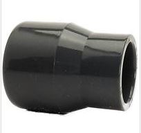
Instead of one length of tubing to hold the 15m element plus two other coiled tubes for 17 & 20m extension hanging off the mast, I have now got all of the wire wound onto the pipe reducer shown abive (after a lot of filing out of the ridge inside it!). the pipe joiner drops over the top of the mast and sits atop the second section of the mast.
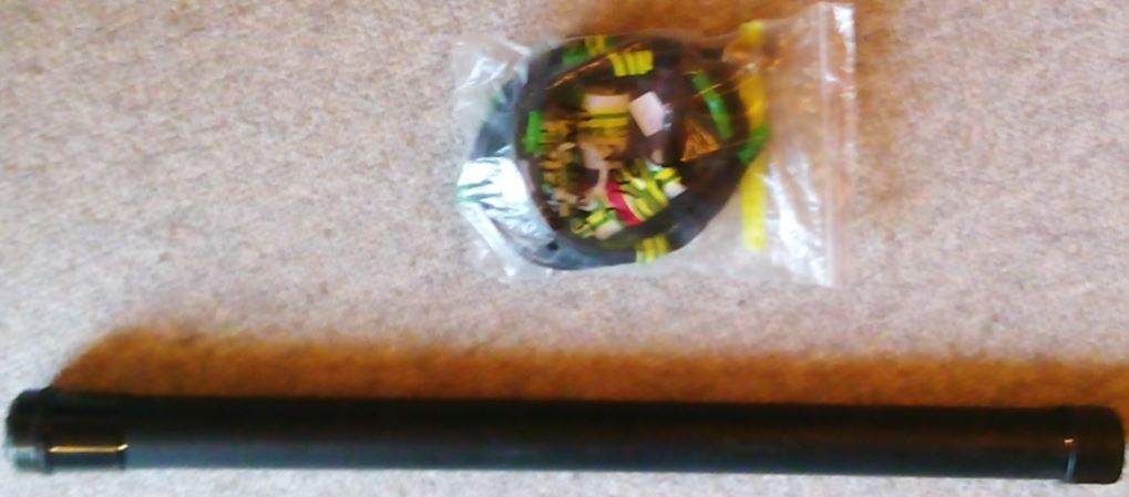
Here’s some photos of the build action:
Tests of new combined construction:
It is possible that using a different mast (about 70cm shorter) may have affected these results however testing the extension wires coiled onto the pipe joiner altered the resonant frequencies of the antennas except for the 20m antenna.
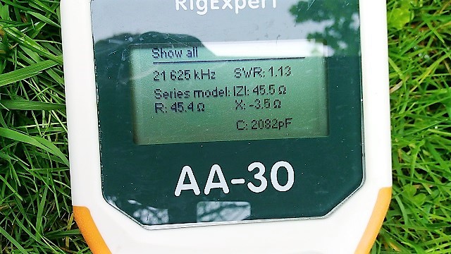
15 Metres – this does not use the extension wire on the pipe joiner and so “should not” have changed however instead of being resonant at 21.285MHz, it now shoed resonance at 21.625 MHz – suggesting the reduced length of the mast being used may be the problem (even though the wire remains the same length). Action: I will retry the test with the full length 6m Lambdahalbe mast.
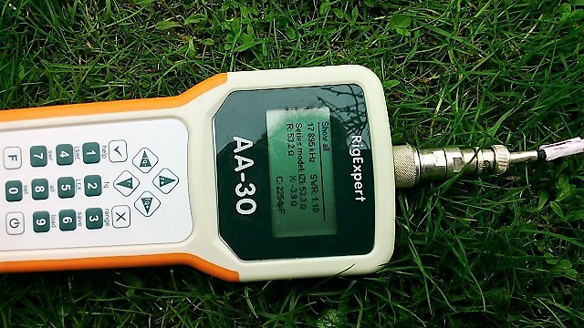
17 Metres was also off, but in the other direction, (now resonant at 17.895 rather than 18.010MHz) which suggests that the rest of the wire for the 20m section being still connected is de-tuning the antenna. Action: I will try adding an extra connector as with the 15m to 17m connection, so that I have links that I close or leave open for each band as appropriate.
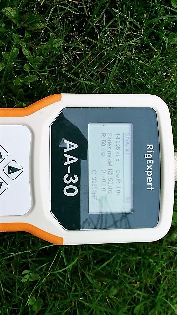
20 metres was resonant at 14.235MHz a little lower than previously but with a better SWR which is fine (the sub 2:1 bandwidth is considerable).
 Re-test 19/4/17.

I am glad to say that my thoughts as to why the combined extension wire / antenna element mounting point caused the resonant frequency to change were correct. While not 100% resonant on the exact frequencies I chose, the antennas bandwidth is so wide that each of the bands are covered at under a 2:1 SWR, which is very good for ANY antenna.

You must be logged in to post a comment.