
To go with my lightweight portable kit, I have been looking for a 40m antenna. For 20,17,15,12&10m I have J-Antennas from lambdahalbe.de who makes a nice product at a silly, cheap price, but only deals within Germany. The J-Pole meets the specifications that I am looking for, to work with my Xiegu G106 “HF Handi-Talkie”, which are:
- Lightweight and small to fit the pack.
- No need for a balun or unun (again to save space and weight).
- Resonant on the required frequency as the G106 has no ATU and I don’t want to have to carry an external one.
- Can be strung from a tree with a cord as I don’t want to have to carry a mast or tripod support with me.
- No need for a set of radials to be laid out so that space is less of an issue.
I could in theory build a J-Antenna for 40m (lambdahalbe only build them for the bands between 20m and 10m) but the support point for the top of it would be very high and impractical. So I decided to look at some kind of antenna that could be strung up in Inverted-V format but not need a mast and not have a feeder cable in the middle. This meant looking at end-fed antennas but whether an end-fed half wave or an end-fed random wire – an unun would be needed and in the case of the random wire, an ATU as well.
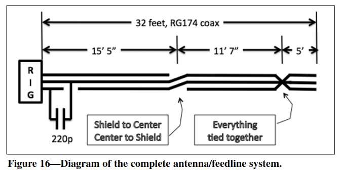
Through my searches, I came across the “Resonant feeder” antennas. The principle here is to use coax for the antenna elements but also to feed the RF up the lower half of the vertical dipole to the centre feed-point of the dipole using the THREE conductors available. Three? What? Well, there’s the centre-core, and the inside and the outside of the metal sheath, hence three possible routes for RF. On the various designs, the simplest I could find was from Ward AE6TY in the article in the Winter 2013 QRP Quarterly magazine entitled “Refining an End-Fed Antenna” at the link below:
Ward suggests using RG174 coax to keep the weight down. I checked but I didn’t have enough RG174 but I did have a reel of 2.2mm thin, 75 Ohm coax. This coax was labelled as “Mini 0.5/2.2 PVC -20°C 201604 146m”. The one downside is that like much of the coax designed for cable or satellite TV usage as I think this is – the braid is aluminium wire+foil and hence very difficult to solder to using normal soldering tools. No matter, for a test – it’s what I had so it would have to do, to prove that the antenna could even work.
Ward’s article and lengths are for 20 metres, so I scaled it up to 40m. I didn’t expect the lengths to be exactly twice as I was using a different type of coax and it’s always better to make the first build too long and then trim back using an antenna analyser. I have a rig-expert AA-30, which when I first bought it, I thought was a major investment but looking back it’s probably one of the best purchases that I have made in the hobby. In any case, having constructed the antenna, I found it was too low in frequency and had a variable SWR between 2.8:1 and 9:1. The SWR problem was a bad connection in the PL259 plug which was quickly rectified. Trimming the very end of the antenna makes no difference whatsoever, all length adjustments have to be made at the centre point where the cables swap over. This means the only way is to take a guess and cut the same amount from both sides, re-assemble the antenna, and raise it back up in the air (I have a wooden flagpole in my garden which is ideal for these kinds of tests). Initially, I took 27.5cm off each side which brought the centre of resonance up from 6495 kHz to 6650 kHz. If the change was uniform (WARNING: It is NOT) a further 62.5cm from each side should put resonance at 7MHz. I decided to cut 40cm from each side and even that was too much, taking resonance to 7240 kHz. at this point however I could see that the bandwidth of this antenna is very wide, I also had not yet fitted the capacitor as per the design to match better and hence bring the VSWR down and I was fairly sure that would bring the frequency back down a little. It did and the updated version of the antenna now has its centre of resonance at 7040 kHz with an SWR of 1.7:1 and the 2:1 SWR points being at 6895 and 7285 kHz. I was rather happy with that!
If you do not get as good an SWR, record the variables on the antenna shown on your analyser and use the Analogue Devices matching network designer at:
In my case, as the intrinsic Inductance was close to the required value, all I needed was a capacitor – in my case a 470 pf rather than the 220 pf one that Ward used on his 20m build, soldered across the PL259 plug.
My dimensions (using the coax I had) for 40m, are 8.725m from the radio plug to the cross-over, 6.386m from the cross-over point to the all wires shorted-together point and 3m from there to the end.
as yet this antenna has only been tested on the analyser so I don’t know how well it receives or sends signals. An antenna that is so broadband is normally not so efficient but of course, the gain advantage of being on top of a mountain may well outweigh the “compromise” performance of the antenna.
Result of portable test of antenna – Failure!
Please see the report here – but unfortunately, this antenna (as I have built it) performs more akin to a dummy load than an efficient antenna!
UPDATE:
Although my test seemed to prove the 40m resonant-feedline-antenna to be a “Dud” – when I tried to re-use the (75 Ohm) coax from that antenna on a simple 40m dipole, it also didn’t tune as expected – so it’s possible that if I rebuilt the RFA using the RG-174 50 Ohm coax specified in the design, it might actually work. The fact that the braid of the 75 Ohm coax could not be soldered as it was aluminium and it had to be clamped to get a connection was never to my taste. I far prefer to solder and know I have a connection that will survive a portable operation.
73 Ed DD5LP.

You must be logged in to post a comment.