
Seeing the good in Solar winds at the bottom of the sun cycle.
It is normal that strong ionised particles escape the sun during a solar flare-up. The number of sunspots (bright spots visible on the sun) that indicate the flare-ups vary over a cycle which can be as short as 7 years or as long as 11. More sunspots equate to a consistent re-charging of the Earths Ionosphere and hence better DX conditions around the globe within the Ionosphere.
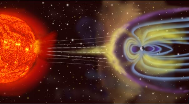
However, charged winds can also be sent from the sun when a shockwave on the sun creates rising gas clouds of solar particles, which get ejected from the sun. These are not Solar Cycle related and are called Coronal Mass Ejections, or CMEs. These travel outwards from the sun at speeds from supersonic to the speed of light and could strike the earth if the trajectory is correct. Often if a “Coronal Hole” appears on the part of the surface of the sun facing the earth, this is also an indication of an earthbound CME.
The CME is made up of:
- A Solar wind of ionizing radiation, electrons and protons travelling at the speed of light (these arrive at the Earth almost immediately and continue for the duration of the event)
- A shockwave that rides along with the solar wind at supersonic speeds.
- Dense particles behind the shockwave that arrive at the Earth 2-3 days after the start of the event.
Signs that a CME event is taking place are noise bursts, buzzing sounds and sudden QSB. These effects are seldom seen on frequencies <10 MHz so look out for these tell-tale signs on 20 metres. It is often worth watching the solar wind speed which after the event has happened on the sun but before the gas cloud hits the Earth often drops below its normal 400 km/sec and as the particles are hitting the earth until the storm passes is above the 400, often above the 500 km/sec mark. This information can be found at spaceweatherlive.com.
Most radio amateurs will tell you that Coronal Mass Ejections from the sun are bad for radio communications and can cause the noise floor to raise dramatically or even cause a total HF communications black out. This is correct. However, there are times during these events when radio propagation actually IMPROVES. This is sometimes referred to as Pre-Auroral Enhancement, as the particles that hit the Earth are what cause Auroras. If you can be around at the right times on the right bands some good contacts are to be made.
The effects on HF bands above 10MHz (30m through 10m) are different from the changes in radio wave propagation below 10MHz (see further down for more details specific to above and below 10MHz).
Re-occurrence of Coronal Hole / CME from the sun.
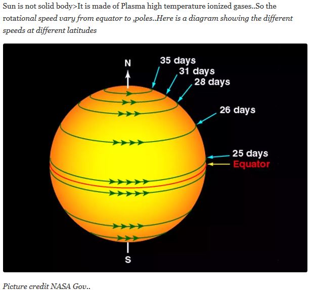
If a coronal hole is large and active, it can return as the sun rotates around (as seen from the Earth’s perspective) and similar conditions in radio propagation can occur again. The time it takes for a coronal hole to return to the Earth facing side of the sun depends upon it’s latitude on the sun:
 Effect on radio communications above 10MHz.
A general rule I went by when starting in HF communications around 2014 (when we were on the peak of Solar Cycle 24), was SFI (the Solar Flux Index which is an indicator of the radiation hitting the earth from the sun) must be over 100 and the K-Index should be 3 or under for the HF bands to be open. Well now in 2018/19 we are at the bottom of Solar activity Cycle number 24 and SFI rarely gets over 70. An SFI of 100 is a dream these days, so it’s important to look at what is possible, despite the “doom and gloom” figures.
SFI or Solar Flux Index is a measure of the ionizing radiation from the sun, and an indicator of the electron density of our ionosphere. The higher the electron density, the more reflective the ionosphere is to HF signals, and the higher the maximum usable frequency (MUF) is. Signals sent out above the MUF travel out into space and don’t get reflected to the Earth.
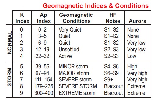
The Kp value indicates the current activity (noise) level in the Ionosphere. The K-Index value is calculated every 3 hours based on the Kp values. The K-indices are averaged over 24-hours to form the A-Index.
When a CME or Coronal Hole event occurs on the sun it sends winds out and those that come in our direction add charged ions to our Ionosphere (the protective invisible “skin” around the Earth). We can think of the protective “skin” as being like an onion with several layers. The ones that interest us are the outer F1 and F2 layers and the inner D layer. The F1 and F2 layers are the ones that reflect the radio waves back to the earth and the more ionised these are, the more effective they are at reflecting the signals. The D-layer is not our friend as it absorbs our radio signals a little (from 2 to 6dB, depending on how well charged it is) and that’s twice for each bounce of the signal off the F layers. (6 dB is one S-point of signal, so go through it twice and your signal is down 2-S points at the receiving station).
Night time is simpler as not only do the F1 and F2 layers combine into one F layer, the D layer disappears, removing the signal loss in the path. Unfortunately, this combined F layer has a lower electron density than daytime levels, which lowers the Maximum frequency of signals reflected by the F layer at night, meaning the “DX bands” like 20 metres don’t work at night for DX contacts, only 40 metres and below keep bouncing signals off the Ionosphere.
So again, it’s important to be on at the right time, on the right band to get those good contacts.
Opportunity Number 1 – immediately after the explosion on the Sun up to dusk.
Once a CME has been spotted on its speed of light (2-3 minutes) way to Earth you should check the higher bands for DX openings for several hours. During this time all the ionisation of the F1 and F2 layers is happening: not only do signals “bounce” better (creating a better signal-to-noise ratio) but the maximum usable frequency also increases. This makes the use of bands above 20 metres possible, where higher gain antennas can be used and there are fewer competing stations. As some of the ionising X-rays will get through the F layers to the D layer, the best time to try for DX on the higher bands is from the point the Solar flare hits up until dusk (when the MUF drops making 20m and up unusable) on the same day. By the next day the D-layer will also have stored some ionisation and it will attenuate your signals on the way to the F layers more than usual. That’s not to say that the second day will not be better than the day before the CME hit, but it won’t be AS GOOD as the first day.
Unfortunately following a CME, at a much slower (but still supersonic) speed, behind a shockwave is a gas cloud of particles which generate wideband noise from 10-20MHz called a Type IV Continuum Storm. This raises the noise floor making the bands very difficult to use. This “Natural Interference” (QRN) can last several hours before it finally clears the Earth to continue on its way farther out in space. At this point in time, disturbances to the solar wind, from a solar flare or coronal hole, can cause serious disruptions to HF by triggering a geomagnetic storm, that in turn can cause radio blackout conditions on HF at higher latitudes. A major geomagnetic storm (K>6) can last 12–24 hours.
Opportunity Number 2 – The LF & MF Bands during the time the storm is hitting the ionosphere.
While a geomagnetic storm causes operation on HF to be difficult, this is an excellent time to work 60–2200M due to very low noise levels on those bands during the storm.
The dense particles in the gas cloud can also include “hard x-rays”, these are classified as “hard” by having > 30 kev of radiation, which strike the Earth’s atmosphere, while showering the earth with ionizing radiation. X-rays from very large events can also penetrate our atmosphere (inside the protective shell), and travel all the way to the ground (this is called a GLE, or ground level event). This can highly ionize the D-layer causing an HF radio blackout through increased attenuation for several tens of minutes.
Effect on radio communications below 10MHz.
The solar flux does not affect the 40metre band and below, whereas the K-index, is more important to us on the <10MHz bands as it indicates the geomagnetic conditions that cause the background natural radio noise.
 Opportunity Number 3 – Better DX on the lower HF bands immediately after the Storm has passed.

As soon as the solar storm ceases (i.e. it has passed the Earth), the Kp Index will drop and night time conditions on 80 & 40M can be excellent as noise levels on 40-80M will often be lower than normal.
Opportunity Number 4 – increasing Critical frequency enabling shorter range contacts.
The effect of the CME from the sun and its extra ionisation of the layers on short distance contacts is measured through the Critical frequency (aka FofF2 or CF).
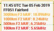
Opportunities don’t always have to mean better DX contact possibilities. On the bands below 10MHz when a Solar strike is happening the Critical Frequency can approach the frequency you are transmitting on. The closer the critical frequency gets to your operating frequency the shorter the “skip distance” becomes. For example, when operating on 40m when the CF is at 5MHz or lower, contacts are only possible from about 4-500 km away, as the CF rises to 6MHz the skip distance reduces and contacts from about 300 km away become possible. When the CF hits 6.5MHz even closer stations at 200km away are workable and finally when the CF is the operating frequency contacts at 100km or even closer become possible.
This is particularly useful for SOTA, WWFF-Parks, some IOTA and Maidenhead Square chasers. DX contacts are not possible on these bands in these conditions but more locations that otherwise are in the “no-contact area” between ground wave and sky wave distances become reachable as NVIS propagation takes place.
Ed Durrant DD5LP 3/1/2019.
HF Propagation times – general rules.
 Critical, Maximum usable, lowest usable and Optimum Working frequencies.
Critical frequency. In telecommunication, the term critical frequency has the following meanings: In radio propagation by way of the ionosphere, the limiting frequency at or below which a wave component is reflected by, and above which it penetrates through, an ionospheric layer. (Wikipedia)
There are a number of frequencies that are of importance when working with ionospheric radio propagation. Frequencies including the Critical Frequency; Lowest Usable Frequency, LUF; Maximum usable frequency, MUF; and the Optimum Working Frequency, OWF are all of great importance when determining which frequencies will provide the best performance for a short wave radio, HF radio communications link.
These frequencies are often mentioned in radio communications propagation predictions. As such an overview of these terms is of importance to anyone using HF radio communications.
Critical Frequency
The critical frequency is an important figure that gives an indication of the state of the ionosphere and the resulting HF propagation. It is obtained by sending a signal pulse directly upwards. This is reflected back and can be received by a receiver on the same site as the transmitter. The pulse may be reflected back to earth, and the time measured to give an indication of the height of the layer. As the frequency is increased a point is reached where the signal will pass right through the layer, and on to the next one, or into outer space. The frequency at which this occurs is called the critical frequency.
The equipment used to measure the critical frequency is called an ionosonde. In many respects it resembles a small radar set, but for the HF bands. Using these sets a plot of the reflections against frequency can be generated. This will give an indication of the state of the ionosphere for that area of the world.
NVIS communications are ONLY ever possible when the CF is at or above the band in use for NVIS. Hence NVIS short range communications WONT WORK on 40m with a Critical Frequency of 5 MHz – but it WILL work on 60m. A useful resource for the UK and Europe to check this is: http://propquest.co.uk/graphs.php?type=NVIS (Note: NVIS ONLY ever works below 10MHz, so don’t expect NVIS on 20m!).
Maximum Usable Frequency, MUF
When a signal is transmitted using HF propagation, over a given path there is a maximum frequency that can be used. This results from the fact that as the signal frequency increases it will pass through more layers and eventually travelling into outer space. As it passes through one layer it may be that communication is lost because the signal then propagates over a greater distance than is required. Also when the signal passes through all the layers communication will be lost.
The frequency at which radio communications just starts to fail is known as the Maximum Usable Frequency (MUF). As a rule of thumb it is generally three (for the F region) to five (for the E region) times the critical and it is true for low angles of incidence, although more exact methods are available for determining this figure.
It is possible to calculate the relationship more exactly:
MUF=CFcosθ
Where:
MUF = Maximum Usable Frequency
CF = critical frequency
θ = the angle of incidence.
The factor sec θ is called the MUF factor and it is a function of the path length if the height layer is known. By using typical figures for the heights of the different ionospheric regions the factors may be determined.
| Region or layer | Distance | |||
|---|---|---|---|---|
| 1000 km | 2000 km | 3000 km | 4000 km | |
| Sporadic E | 4.0 | 5.2 | ||
| E | 3.2 | 4.8 | ||
| F1 | 2.0 | 3.2 | 3.9 | |
| F2 Winter | 1.8 | 3.2 | 3.7 | 4.0 |
| F2 Summer | 1.5 | 2.4 | 3.0 | 3.3 |
MUF factors for various distances
assuming representative heights for the principle ionospheric regions
An “operational” format for the maximum usable frequency may also be seen on occasions. This is the maximum usable frequency, MUF that would permit acceptable operation of a radio service between given terminals under specific working conditions. This form of MUF has the emphasis on the operational acceptability of the circuit. It means that factors such as the antenna, power levels and such like are considered and gives an indication regarding the possibility of real communication at a given station.
Relationship between MUF & skip distance.
MUF readings are always given from a particular position and for a specific distance. In some cases a MUF can be calculated for a particular A to B signal route.
Why is a MUF frequency value given for e.g. 100Km, 500km, 1000km & 3000km?
To understand this we also need to understand a bit about skip distance – i.e. The distance from your QTH where your signal that is shot up into the Ionosphere comes back down to Earth (possibly to bounce back up to the Ionosphere go further) is your skip distance. How the Ionosphere (and in particular, the F1 and F2 layers) reflect your signal depends on two factors – the frequency of your signal and angle the signal meets the layer.
Depending upon how much ionisation charge the layer has, the high the frequency of the signal it will reflect back to Earth. This is the Maximum Usable Frequency (MUF) and if your signal is higher than this – it will pass through and shoot off into space, never to return.
The angle of your signal hitting the F-layer will be reflected in the angle that the signal comes back down to Earth. The shallower the angle, the further away the signal will come back down. This is why DX antennas try to get a very low angle of radiation. Ideal would be if all the signal went to the horizon as that would give it the maximum distance. While talking about antennas. A Yagi antenna is measured as having a gain. This is NOT the same as the gain that an electronic circuit gives, like the PA stage of your rig or linear amplifier – that takes power in from the PSU uses it to give a proportional output signal to the one feeding the amplifier. There is no DC supply to an antenna and so it would be getter to say that an antenna “concentrates” the power it gets into a restricted direction. In the case of DX, this means concentrating it in the direction of the land that you hope to talk to. Stacked Yagis can also concentrate the signal in the vertical plane and hence “fire” the signal at the horizon better to get a shallower angle hitting the F layer and hence a longer distance.
The further the skip distance is, the higher the frequency is that the F-layer will reflect. Think of the difference of a “glancing blow” when skipping a stone over a pod, and a direct hit down into the pod with your stone. The direct hit breaks through the surface and keeps going, the glancing blow stay above the water (or in radio terms stays within the ionosphere to be able to come back down and possibly bounce again). Of course if a really shallow angle is achieved it should be possible to bounce off one piece of the Ionosphere across the sky and onto to another part of it without having to reflect off the earth.
This means that as the distance increases the MUF also increases – example from propquest:
 If we could achieve a 5000 km skip – the maximum usable frequency would probably be up around 21MHz (15m). This is one of the reasons that the “super stations” with their stacked beams can achieve distances that other stations cannot. Of course power helps as well as every bounce up to and down from the F layers has to go through the D-Layer of the Ionosphere and it is not our friend as it attenuates the signal. The higher charged it gets the more it attenuates. To compensate for this more sensitive receivers and more power at both ends of the path are needed to make the contact.
Lowest Usable Frequency, LUF
As the frequency of a transmission is reduced further reflections from the ionosphere may be needed, and the losses from the D layer increase. These two effects mean that there is a frequency below which radio communications between two stations will be lost. In fact the Lowest Usable Frequency (LUF) is defined as the frequency at below which the signal falls below the minimum strength required for satisfactory reception.
From this it can be seen that the LUF is dependent upon the stations at either end of the path. Their antennas, receivers, transmitter powers, the level of noise in the vicinity, and so forth all affect the LUF. The type of modulation used also has an effect, because some types of modulation can be copied at lower strengths than others. In other words the LUF is the practical limit below which communication cannot be maintained between two particular radio communications stations.
If it is necessary to use a frequency below the LUF then as a rough guide a gain of 10dB must be made to decrease the LUF by 2 MHz. This can be achieved by methods including increasing the transmitter powers, improving the antennas, etc..
It is found that the LUF actually increases in periods of high solar activity. This is arises because of the increased levels of solar radiation that give rise to higher levels of ionisation in the D layer. This in turn increases the level of attenuation introduced by this layer. This means that at the peak of the sunspot cycle there is degradation in the performance of the low frequency bands for long distance communications.
Optimum working frequency
To be able to send signals to a given location there are likely to be several different paths that can be used. Sometimes it may be possible to use the either the E or the F layers, and sometimes a signal may be reflected first off one and then the other. In fact the picture is rarely as well defined as it may appear from the textbooks. However it is still possible to choose a frequency from a variety of options to help making contact with a given area.
In general the higher the frequency, the better. This is because the attenuation caused by the D layer is less. Although signals may be able to travel through the D layer they may still suffer significant levels of attenuation. As the attenuation reduces by a factor of four for doubling the frequency in use this shows how significant this can be.
Also by increasing the frequency it is likely that a higher layer in the ionosphere will be used. This may result in fewer reflections being required. As losses are incurred at each reflection and each time the signal passes through the D layer, using a higher frequency obviously helps.
When using the higher frequencies it is necessary to ensure that communications are still reliable. In view of the ever-changing state of the ionosphere a general rule of thumb is to use a frequency that is about 20% below the MUF. This should ensure that the signal remains below the MUF despite the short-term changes. However it should be remembered that the MUF will change significantly according to the time of day, and therefore it will be necessary alter the frequency periodically to take account of this.
HF propagation – general “time of day” rules for HF bands:
Answer 1 – General guidance:
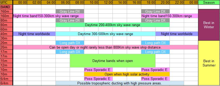
In general, the shorter wavelength HF bands are better during the day, and the longer wavelength ones at night. Although that depends a bit on what you want to do, and like all things propagation, it’s subject to change. Let me try and give a rough mode of operations. Also take a look at the chart from eham.
4m/6m- Randomly opened, in random directions. I think this happens more in the day, but I’m not a 6m expert. Strictly speaking this is VHF, not HF. Possible Sporadic E late morning and Early evening.
10m- This is more consistently opened, especially in times of higher solar activity. Evening tends to be the best time, at least that’s what I’ve found, but this is a daytime band. Possible Sporadic E late morning and Early evening. SFI Dependant.
12/15/17m- These are traditional daytime bands, usually opened. The longer the band in this window, the more reliable it is, and the more likely it is opened night or day. SFI Dependant.
20m- Can be opened day or night. This is the most reliable band for dx. Early morning has Long Path. Variable skip distance but often nothing under 800Km by skywave. SFI Dependant.
40m- Daytime is opened in a “local” area, give or take 500 km or more with a good set up. Night time opened worldwide. Variable skip distance but often nothing under 300Km by skywave. Less SFI Dependant.
80m- Similar to 40, but even more extreme. Greyline propagation in morning and evening very relevant. Not SFI Dependant.
160m- This one is only opened at night, and tends to be a more local area. Not unlike 6 meters, strictly speaking this is MF rather than HF, but it’s often included on HF rigs. Greyline propagation in morning and evening very relevant. SFI Dependant.
Answer 2 – more detailed
HF propagation over long distances is by skywave propagation, the reflection and refraction of radio waves between Earth’s surface and the ionosphere. The ionosphere is a consequence of radiation from the sun ionizing Earth’s atmosphere, so it changes significantly with time of day and sunspot activity.
Although time of day is just one of many variables, here is a simplified model of the ionosphere:
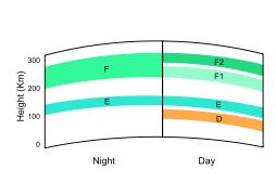 The F layer is mostly responsible for the refraction of radio waves back to Earth, preventing them from escaping to space. The other layers interact in other ways. During the day, the D layer forms, and the F layer splits into F1 and F2 layers.
The D layer is present during the day and is a good absorber of radio waves, increasing losses. Higher frequencies are absorbed less, so higher bands (20m to 10m or so) tend to perform better. Above the critical frequency, the ionosphere is unable to refract the signal back to Earth and it escapes to space. The critical frequency during the day is in the neighbourhood of 6m: depending on the space weather, 6m way work for skywave, or it may not.
During the night we need not contend with D layer absorption, but the critical frequency is lower, so higher frequencies can not support skywave propagation. This can be observed on a map of critical frequency: see that the critical frequency is typically lowest around dawn, when the ionosphere has been in the dark the longest.
So, very rough rule of thumb:
20m, being in the middle, works to some extent day or night.
Lower frequency bands work best at night.
Higher frequency bands work best during the day.
The farther from 20m you get in either direction, the more pronounced these effects are.
Of course, given that space weather is just as variable as Earth weather, there are exceptions to these rules every day.
Chordal Hop and Long Path
I just learnt something about why long path often gives stronger signals than short path on 20m and above – Chordal Hop. It seems that when signals go long path (and hence normally around the dark side of the Earth) they can bounce around within the Ionosphere without coming back to bounce off the Earth, which of course reduces the path losses and increases dramatically the distance of each hop when it does come back down to Earth for those hops. It’s somewhat the HF equivalent of VHF temperature inversion signal ducting only at a lot greater height and hence over a longer distance.
This also explains the when Long Path is open to the UK from VK it’s already closed to Central Europe and why I, in Southern Germany) am more likely to get Long Path to the east Coast of VK (VK2/VK4) and Mike in northern UK is more likely to get Long Path contacts into VK3 and VK5.
Further on Chordal Hop from PA9X (webpage )
Signal that bounces along the ionosphere
Chordal hop propagation is a propagation mode involving the daylight F2 layer and night time F layer. At daytime there are two upper layers in the ionosphere, the F1-layer at ± 150-200km and the F2 layer at 250-400km. Shortly after sunset these two layers merge into the F layer and split up again into F1 and F2 layer at sunrise. During night time the F layer loses it’s ionization density, and it’s ability to reflect signals back to Earth. But sometimes the F-layer is just dense enough to reflect the signal back, but with a less steep angle, causing the signal to be directed to another part of the ionosphere thousands of km’s ahead, not touching the ground. Here is a picture I have drawn to visualize.

Less attenuation with chordal hop
With chordal hop propagation you have much less attenuation due to the fact the signals do not reflect against the Earth’s surface. In this situation the signal that uses long path propagation arrives at the other station with much less attenuation, thus with a stronger signal than the short path. One unusual thing is that a station at night time, like imaginary Brazilian station PY4FTL in Rio de Janeiro, has signals travelling far above him through the ionosphere, but he cannot receive them.
Amazing stuff this propagation!!

You must be logged in to post a comment.