
A backpack portable HF Beam? Yeah right!
It does work! The two-element, single mast, HF Beam described below, on recent SOTA activations has brought 20w SSB contacts with W, ZS, VK and ZL as well as most European countries from DL.
Sounds too good to be true? Well, remember the physics of antennas don’t really care whether the equipment has got some big company name on it or not, as long as it’s the correct size and set up close to the way needed, it’ll work no matter how scruffy it looks and running low power means it can be made backpacker portable. I have created three different versions of the antenna, each of which can be single or multi-band by the use of trapped elements.
Two element, single-mast, multi-band wire beam antenna with the option to have 4 locally or remotely switchable directions
What is a beam antenna? It is a directional antenna which “concentrates” the available signal in a particular range of angles in both azimuth and elevation. It does not “amplify” a signal as an electronic amplifier does even though antennas are quoted as having so many dB of gain, that gain is achieved through concentrating not through adding extra power from another source.
What is the main advantage of a directional antenna over an omnidirectional one? Some would say this concentration of signal, putting it where it needs to be (for example near the horizon for DX communications) in the main measurement but just as important is the ability of a directional antenna such as a beam, to reduce the unwanted signals coming in from other directions!
SCOPE OF REQUIREMENTS:
A portable antenna with gain through directivity that can be easily transported to a portable location and set up.
This article will cover four versions of the antenna with the design strongly based on the design from Chavdar Levkov Jr. LZ1ABC and Chavdar Levkov LZ1AQ from 2017
- The first version described below was actually the last built as it was built to find where faults were in the final “all singing and dancing” version. This version is the basic wire antenna with no direction switching.
- The second version adds direction switching through the addition of a rotary switch on the feed-point board.
- The third version adds remote (cableless) switching performed by an IoT (Internet of Things) relay board using Bluetooth controlled from an Android Smartphone.
- The fourth and final version is an add-on to any of the first three versions. It adds multi-band capability through the use of traps in the antenna elements. By having traps in the elements, we can use the same antenna on e.g. 20m or 10m or indeed 20, 15 and 10m! The example described here worked on 20m and 10m but after writing has had 15m added and even 40m is under consideration.
EXPANDED SCOPE OF REQUIREMENTS:
The requirement for all four versions is to create a cheap and simple-to-construct portable antenna that will perform better than the usual dipole, end-fed or omnidirectional vertical antenna used on Adventure Radio scheme portable activations (there is, of course, no reason why these designs should not also be used by a home station).
The detailed requirements are:
- single mast support
- lightweight
- impedance that will be in the range of the built-in automatic tuners of the modern transceivers
- gain through antenna directivity
ANTENNA THEORY
The single mast requirement led LZ1ABC & LZ1AQ to adopt the use of a pair of inverted V dipoles. An antenna type well known to portable operators and a trusted design. The guys did some research first by trying several models in MMANA (see diagrams later) their results indicated that it was theoretically possible to obtain acceptable directional properties with two opposite-placed sloped inverted‑V antennas however the antenna impedance may provide an issue as it would be quite low due to the closely spaced elements. (Note: in this case, the “Inverted-V” elements are V’s in two directions – from the mast top down to the ground and seen from overhead).
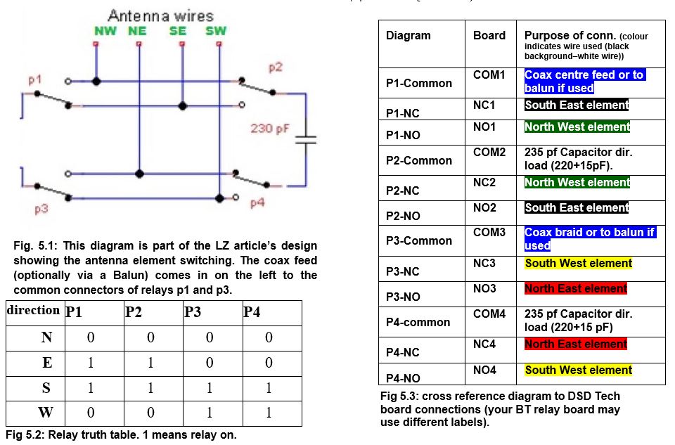
DK3BA wrote an article in the December 1 2011 edition of QST magazine for a 2-element beam switched in 6 directions in which he clarified that the feed impedance could be controlled by using the correct angle to the vertical of the sloping Vs. DK3BA’s design is for 6 switched directions which adds complexity – so LZ1ABC & LZ1AQ decided to implement this design but only for 4 directions. This is the design that we will document here. The antenna is shown in Fig.1 and Fig.2(a & b) and consists of 4 equal-length sloped wires which are connected as two inverted-V opposing elements. The beam consists of a driven element and a director.
Misnomers:
- A dipole has to be horizontal – not an Inverted-V dipole, it is fed high in the middle and the ends drop down.
- A Dipole has to run in a straight line – no, while this makes it easier to see where the lobes will be, a dipole will still work when “bent”.
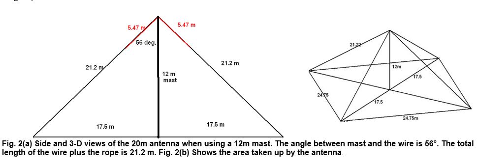
The inverted V that takes the role of director is electrically shortened with a capacitor (Fig.1). The length of wire required will depend upon its diameter and whether it is insulated or not. The portable-antennas.com website has an online calculator for linked dipoles which can also be used for this antenna. The later table gives element and extender cord lengths (the element + extender cords form the guying support for the mast) the values given ensure that the important 56° angle between the mast and the wire elements. If your configuration has the antenna feed-point below ½ λ AGL the radiation pattern will be affected.
In the LZ1ABC & LZ1AQLZ build of a 20m model used 5.47 m of 1.2 mm bare copper wire Fig.2(a). The design’s centre frequency was 14.1 MHz. The area occupied by this antenna is shown in Fig.2(b) where the antenna rope ends are denoted. The angle at the top of the mast must be 56°. The bandwidth (SWR 2:1 or better) is about 200 KHz. Outside of this frequency range, an ATU can be used to make the best of what is there. A 50 Ω coaxial cable (e.g. RG-174, RG-58) feeds the antenna as long as power is not over 100W.
The generally available compact portable telescopic fibreglass masts are usually 6m, 7m and 10m and hence the table below gives the details for the use of those masts. If you wish to build this antenna for lower bands, higher masts will be needed.
If you have a different length mast, try your own combinations of mast height, peg height and combination of bands using the calculator located at www.portable-antennas.com
Here is a table of values for bands based on the feed point being at 5 and 9m heights above ground and NO end rope support poles. The wire is a standard insulated hook-up wire (93%).
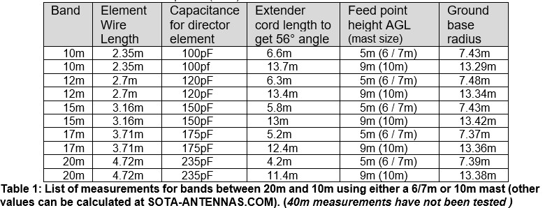
In an article on their „4DX“ antenna in the October 2024 RSGB RadCom Magazine, VK6VZ & VK6LW suggest increasing these capacitor values by 30% for added gain. They also recommend higher mast heights for the lower frequencies.
GENERAL DATA FOR THIS ANTENNA:
This basic design is a single-band beam antenna with a driven element and a director that provides;
- 2% frequency bandwidth (e.g. 280 kHz on 14MHz, 560 kHz on 28MHz)
- 10 dB F/B ratio
- ~5 – 8dBi gain
- 25 – 30° vertical radiation angle
It has a reactive load (for 20m, a 235pf capacitor- see Table 1) to shorten a pair of the equal-length elements to act as the director. This capacitor (or series/parallel capacitors) needs to withstand high voltages. An estimate is the PEP output power in watts times five in volts, so for example, with 100W PEP, the capacitor (which ideally would be mica or silver mica type, but ceramic will do) needs to be rated to 500V.
The four “half-elements” form the support guys for the mast, which for the 14, 17, 21, 24 & 28MHz versions can be a 6, 7 or 10m fibreglass pole (feed-point needs to be at least 1/4 wavelength above ground).
The inverted-V form elements require a 56° angle from the mast to the wire, and to do this, the extender cords on the ends of the elements need to be of a measured length to keep the angle correct at the feedpoint. The radius of the pegging “circle” is 1.5 x the feed-point height.
While intended to radiate in a single direction, as long as the feed plate is allowed to turn on the mast, it could be possible in a portable operation to rotate the 4 elements/guy cords as required to change direction (although the full design with relays on the feed plate is more practical).
At QRP power levels, a direct 50Ω coax feed to the driven element keeps construction extremely simple; however, for higher power levels, the inclusion of a 1:1 Balun transformer at the feed point is advised, as is a higher voltage capacitor.
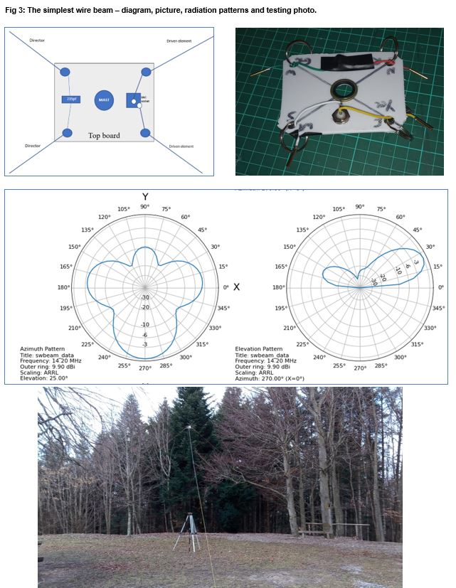
DESIGN Number 1 – Basic – no beam direction switching.
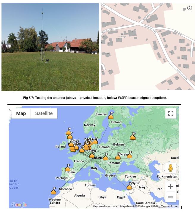
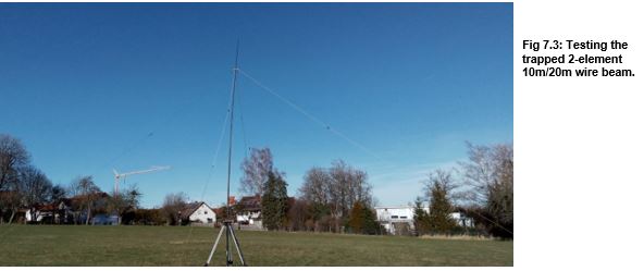
Below are shown the feed point board and the calculated radiated field diagrams. The board is made from part of a kitchen cutting board with a central hole with a rubber-centred “USIT” washer to grip the F/G mast a simple BNC coaxial socket and in each corner an arrangement using a metal key ring and 2mm RC battery connector connectors which clip into plugs on the ends of the 4 element wires. One pair of wires connect to the BNC socket and the other two are connected together via a 235-pf capacitor (made from two wired in parallel to get the correct value. Below the signal radiation diagrams (note the large side lobes) is a picture of the first test of this antenna, which achieved two South African and one USA contact using 20 watts of SSB on 10 metres.
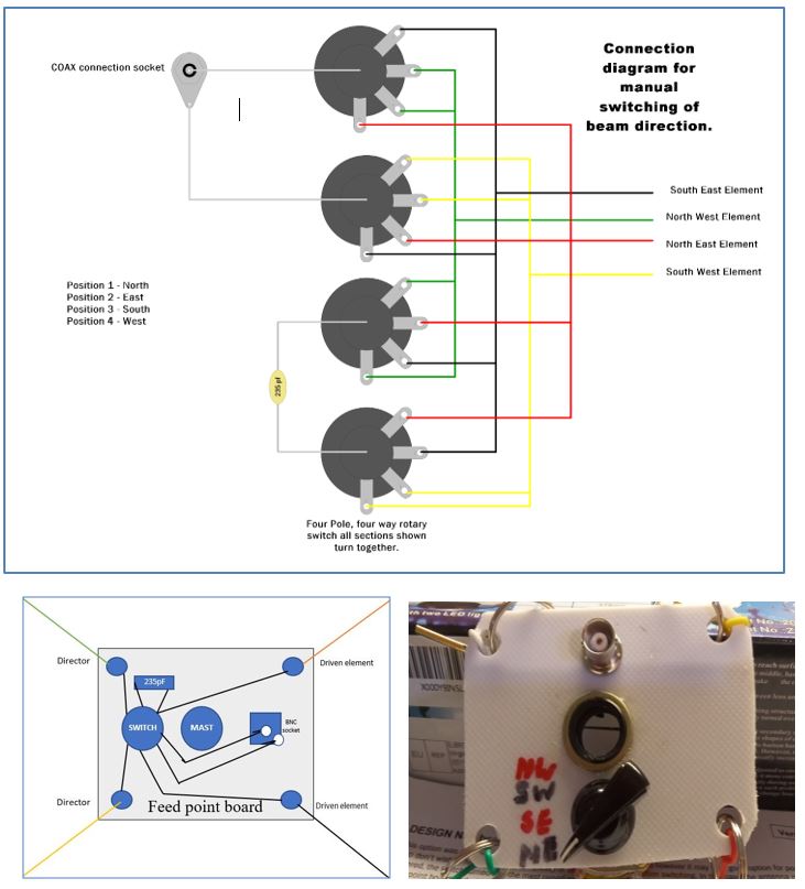
DESIGN Number 2 – Addition of basic beam direction switching.
This option was also mainly built to test the antenna; however, it may be a good option for portable operators who don’t wish to have the extra complexity of electronic beam direction switching. In this case, the antenna mast needs to be lowered, the switch turned, and the mast raised again when a different radiation direction is required. The switch is added to the feed-point board and wired as shown below (note: after usage of the antenna on several activations, I found that I would prefer labelled antenna directions to be N, E, S and W, so the elements now need to be run out in NE, SE, SW and NW directions, not as in the original design):
Fig 4: Using a 4P4T rotary switch to change the antennas’ radiating and receiving direction:
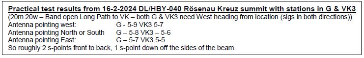
DESIGN Number 3 – Full beam direction switching via Bluetooth.
This is the main design and goes into more detail about the components used; however, the principal design has not changed. This is still two Inverted-V dipoles acting as a 2-element beam antenna.
Antenna element Switching.
On the feed-point board (a larger one than in the previous two designs), an IoT BT 4 relay board is mounted with a LiPo battery, as is the connection to the RG-174 feeder coax via a 1:1 balun (optional at QRP levels).
Feeder
As long as low power (less than 40 watts) is used, RG-174 or RG-316 is adequate, as well as being lightweight. If this antenna were to be built for higher power usage, larger coax would be needed.
Capacitor
The capacitor value needs to be close to 235pF (this could be made using standard values in series or parallel as required to get the value – e.g. 220 + 15 pF). Important is, that these capacitor(s) need to be capacitors with at least a 500 V working voltage, ideally silver-mica. Low-loss ceramic capacitors can also be used if silver mica cannot be sourced. The voltage across the capacitor depends on the power in use. At 100 W RF power, the peak voltage will be approximately 100 volts into the 50 Ω load. At this power, NEC2 gives approximately 2.0 A peak current in the director wires. At 14.25 MHz, a 235pF capacitor has a 49 Ω impedance, so approximately 100 V peak voltage will develop between the capacitor terminals.
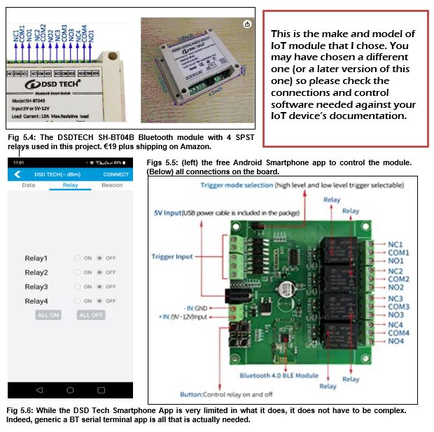
IoT Relay boards
These boards are cheap and available on both eBay and Amazon – you could not build these boards for the price they are sold at.
They come as either Bluetooth or WiFi-activated boards and I will also include with these boards as an option, the 433 MHz ISM “garage door opener” kinds of boards which, while not having anything to do with the Internet, still use the same relay boards and are available with the required 4 SPCO relays and these have the advantage that they use a 4-button key fob rather than a Smartphone activate them. (far easier to use on a mountain top in -10°C temperatures).
The DSD-Tech Bluetooth one documented here also come with a housing. The distance away you can operate the relays (which latch in the selected setting until changed) is officially 10 metres. – This means that your smartphone won’t switch the relays (and hence the antenna) if you move too far away from the mast. The board you chose needs to have 4 SPCO relays to do the needed switching.
Do you need a Balun at the feed point?
To stop common-mode currents on the coax, a 1:1 balun is sometimes needed, but often is not, especially if only running up to 20 watts. The 1:1 current balun can take the form of the feeder coax wound around a former, clamp-on ferrites on the coax cable or a proper ferrite transformer balun unit. My advice (especially if running low-power) is to try without starting with and only add if needed. If needed, the coiled coax is most likely the simplest and certainly the cheapest solution.
Losses
Theoretically, estimated losses in the system are 0.3 – 0.4 dB for a 25.5 m feeder; 0.2 – 0.3 dB in any balun used (optional alt low power); 0.2 – 0.3 dB in the rig’s internal antenna tuner. The total losses are expected to be in the order of 0.7 – 1 dB, which is more than acceptable, especially for a portable installation.
Needed materials to build this antenna:
- Antenna top module – A “platform” made from a plastic kitchen cutting board has the relay unit and Balun mounted on it, the corners of the (square) board are drilled, and key rings and carabiners are added to support the 4-element wires. A hole in the middle of the board, where the mast comes through, is strengthened on each side with “USIT” washers. These washers have a rubber ring in them and are usually used for mounting brake pipes on cars, where the rubber centre ring reduces vibration. In our case, it avoids too much stress being put on the fibreglass mast. With the weight of this board, it is recommended to use a heavier-duty mast or the lower sections of a taller mast. Keep the wires going from the relay module to the corners as close to the same length as possible as these form part of the element lengths. Also, avoid these wires crossing each other.
- Antenna wire – enough for 4 quarter-waves on the band of choice for a single-band (e.g. 20m) antenna. Cut to length based on the table above or the output of the calculator at portable-antennas.com (don’t forget to set the correct wire size and whether it is insulated or not before running the calculation).
- Fibreglass mast – here you need to decide whether a “standard” mast with long sections (in heavy, medium or light-duty models) or one that is meant for travel is to be used. You also need to choose a height and select the extender cord measurements to suit (and still have the 56° angle between the wires and the mast). Masts are available as 5,6,7,8,10 & 12m in various strength levels. Apart from the heavy‑duty masts, the top one or two sections of a mast are normally too weak to be able to be used. What this means is to get the antenna centre up at 5m, you will need a 6m mast and for 6 metres a 7 metre one, etc.
- Pegs for guy ropes and antenna element extender cords
- 3 guy ropes for the mast (only if using a larger mast, where these guys will be connected at about half height)
- 4 antenna extender cords for the 4 antenna wires
Some way to support the mast, e.g. a screw-in sun umbrella base, a tripod or even just a wooden pole of the correct diameter to fit inside the mast when the base plug is unscrewed.

Platform details
- A €3 kitchen cutting board was bought and cut to be square. Holes were drilled in it for the mast (14.1mm in my case) in the middle. 4 corner holes and one hole to feed the coax cable through. On this, the Bluetooth relay board and the 1:1 Balun were mounted.
- A PP3 battery to power the unit fitted inside the relay unit (later replaced with a Lipo battery) and an on-off switch was added.
- Keyrings were added to the 4 corner holes on the board where the element wires will clip into using carabiners for strain relief.
- Short patch leads were added from the relay board to the corners for connection to the 4 elements using 2mm gold-plated RC power connectors.
- Patch wires across the needed terminals on the relay unit, and a 235pf capacitor (director element loading) was added (220pfd + 15pfd in parallel).
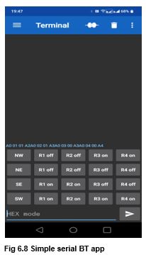
Bluetooth serial commands:
These are the command strings needed by the DSD-TECH SH-BT04A board it is a one-way communication (there is no confirmation of receipt of command):
Control instructions (Hexadecimal format):
- Relay 1 ON: A00101A2 OFF: A00100A1
- Relay 2 ON: A00201A3 OFF: A00200A2
- Relay 3 ON: A00301A4 OFF: A00300A3
- Relay 4 ON: A00401A5 OFF: A00400A4
Explanation:
To switch a relay on or off, we send a 4-byte command packet in the format:
- Byte 1 = Sync/Header = A0 (hexadecimal)
- Byte 2 = Relay Number: 01 = first relay, 02 = second relay 03 = third relay 04 = forth relay
- Byte 3 = Relay State: 00 = off, 01 = on
- Byte 4 = Checksum = sum of preceding bytes (e.g., Channel 2 OFF = A0 + 02 + 00 = A2)
Note that these are not ASCII terminal commands, so don’t add any end-of-line characters; otherwise, the commands do not work. A character delay of 10ms and line delay of 5ms seems to work fine when using the serial Bluetooth terminal App.
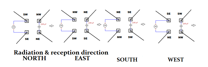
The following commands “turn” the antenna to:
- NORTH: A00100A1A00200A2A00300A3A00400A4
- EAST: A00300A3A00400A4A00101A2A00201A3
- SOUTH: A00101A2A00201A3A00301A4A00401A5
- WEST: A00100A1A00200A2A00301A4A00401A5
The downside of this solution is that multiple commands need to be sent from the Phone app to “turn” the beam, and you cannot tell from the ground if you have missed one, so the wrong wires may be connected for the desired direction. It is hoped to develop a “one-button” solution where we can be happy that the correct wires are attached for the direction chosen. Perhaps with a “garage door opener” remote control board mentioned earlier under IOT relay boards.
Space required for antenna:
The radius of the ground needed to install the antenna does not depend upon the band but rather the height of the mast. So (within operational tolerances), if using a 10m mast (9m height) you need a circle of land with a radius of about 13.4m. When using a 6m mast (5m antenna height) you will need a circle of land of about 7.4m radius. So, the radius of land required is 1.5 times the height of the antenna at the feed point.

DESIGN Number 4 – Multiband versions of the antenna.
These changes can be applied to any of the previous three designs documented to change them from being a single-band antenna to one which supports multiple bands.
In theory, when you switch bands, you should also change the capacitor that shortens the second element to be a director; however, I have found that with the higher HF bands (20m – 10m), the impact of not doing so is very little, and the 235pF is “close enough”. If you were building this antenna to support 30m or lower bands, you would need to consider the capacitor value and some way to change it as you change bands.
To do this, we cut the wire of the lowest band to be supported and add one or more traps that are built for the frequency of the additional band(s) and placed at the correct length down from the feed-point board for the band in use. This has to be done on all four elements as we change the frequency of not only the driven element but the director element as well.
There are plenty of designs on the Internet of how to create traps, but in our case, we are looking for the lightest weight while still handling the power to be transmitted through the antenna. Some companies provide kits to build traps. Those based in the UK should take a look at the kits from SOTABeams; however, if, like me, you live in the EU, I have found a Dutch supplier, HFKITS.NL, which avoids the major hassles of buying from the UK since Brexit. Those outside of Europe should look for their own local supplier or build from scratch.
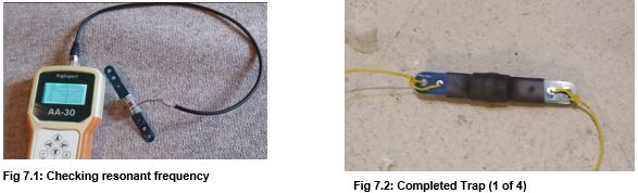
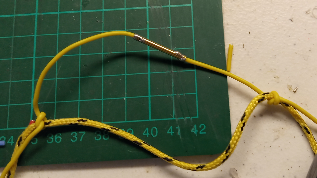
For my conversion, I ordered four low-power trap kits from HF-Kits (www.hfkits.nl) in Holland and built them for 10 metres. These traps are well thought out, using the capacitance of the PCB itself against a coil wound on a plastic tube that the PCB sits within. A method of measuring and adjusting the coil spacing is needed to get the trap on the required frequency. A grid (or nowadays gate) dip oscillator is ideal but some Antenna Analysers can also perform the required function by simply adding a loop of wire to the analyser’s socket placed near to the tuned circuit. My RigExpert AA-30 has this capability. The trap resonates at the bottom of the desired band, making the RF signals on that band (in my case 10m) see the trap as the electrical end of the antenna wire however lower frequency RF (e.g. 20m) will just see the trap as part of the length of the element continue to the end of the remaining wire section of the antenna.
Once the traps are built and inserted at the calculated position in the antenna elements, you will need to re-trim the elements to the correct length for the part of the bands that you wish to use the antenna on.
In the case of the higher frequency band, you can change the length (longer wire = lower frequency, shorter = higher frequency) at the feed-point end of the elements. For the lower frequency band, you will need to trim (or add to) the end of the wire elements to which the extension (guying) cords are tied. To help in this action, you can tie the cord a little way up the wire section and let the remainder of the wire (a couple of inches) “dangle” down – the length of the wire seen in the antenna does not stop at a knot, it continues on to the actual end of the wire.
Using linked rather than trapped elements.
The use of links in a simple portable antenna is quite common, especially in inverted-V antennas. Well, as this antenna is made up of two Inverted V dipoles, why not links as well? The downside of course is the same as with a linked dipole, you must lower the antenna to change bands, which is not needed if using trapped elements, but for some amateurs, this may be acceptable in their portable operations situation; the reduction in weight to be carried may be worth the inconvenience in operation. Some also say that traps in an antenna element lose a little bit of your signal.
Normally, you would need to have some piece of non-conductive material (e.g. plastic) at the breakpoints to support the link plug and socket, but why not keep it really simple if you (like me) use a non-conductive support cord, you can simply tie the wire to that at the point where you want the link to be (see Fig 7.4). For a 20,17,15,12,10m linked element of the beam, the dimensions can be calculated using the Inverted-V linked dipole calculator at sota-antennas.com. Remember to cut long and trim with the help of an antenna analyser.
Your values will most likely be different, but my link wire lengths are 2.5m, 0.4m, 0.5m, 0.6m, and 1.1m (starting from the feed point outwards to the end of the wire element).
So, What’s Next?
Well, what if you find yourself out portable, only to find there is not enough room to put up the beam?
Well, since in this last step you have created effectively two linked dipole configurations, just take two of the beam element wires and attach them to a two-connector feed-point plate like the one below, which, being so small, can be easily packed in with the beam “just in case”.
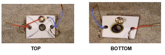
As well as being a dipole feed point for a simple antenna, this simple solution also doubles as a tool to trim new elements or re-trim them after adding another trap into them. The antenna elements (whether trapped, linked or straight) fit all of the different feed-point solutions shown in this article.
“Building a better mousetrap”.
All of the designs above are valid in their own areas – whether it is simplicity with just one band and one direction, or one band with mechanically switched directions. Or with multi-band models using either links or traps. Up to the Bluetooth-controlled version.
But with this top version – remote controlled and multi-band, it still isn’t “fool-proof” enough for me as, when using a Smartphone to control the relays, several actions are required to get the antenna to point in the desired direction. Yes, with a better app for the smartphone, with support for scripts, we could get to a single button antenna switching option however, we still need the smartphone, which being a multi-purpose device has the risk of something not operating as expected.
For an antenna, especially a portable one – things need to be simple and robust.
DESIGN Number 5 – Along comes the “Garage Door opener – key fob” option:
These remote-control devices use the 433MHz ISM band and hence are probably not good for use at a VHF field day where there is a high-power 70 cm amateur station on the air, but apart from that, this direction does offer a simple key fob solution which is better (IMHO) than using an App on a Smartphone.
The principle is very similar to the earlier Bluetooth (or WiFi) solution – the relays are controlled remotely from the ground to switch the antenna direction; however in this case, rather than using a Smartphone, a Key fob is used.
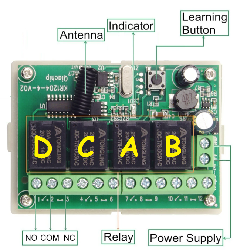 Fig 8.1: The ISM receiver board and relays, and a 4-button key fob Fig 8.1: The ISM receiver board and relays, and a 4-button key fob |
While this approach simplifies the ground side, it does add complexity to the feed point platform. After all, we still need to switch the 4 elements around between connections. The receive board for the key fob can only switch the 4 relays, either locking them or intermittently closing them as each of the 4 keys on the fob is pressed. There is, however, a board
configuration where when one relay is engaged, all others are disengaged. This gives us logic on the antenna feed point board where we now have a live trigger line that corresponds to the button (direction) pressed on the key fob saying that the antenna needs to be switched to N, E, S or W (corresponding to A, B, C & D on the key fob). Using the four trigger lines to close or open the appropriate relays on a second relay board which will configure the antenna wires as needed. I initially had a 5V ELGOO 4-Relay board, but found that it had to be triggered from a microcontroller data line. I searched on Amazon and found an alternative YWBL board ( https://www.amazon.de/dp/B07QL1TFFW ), where lifting the trigger line either high (to 12v in this case) or low (Earth) would switch the relays as required.
The wires from the ISM receiver board relays are connected via signal diodes to the trigger connectors on the new relay board, as shown in Figure 8.3 below.
If we consider the relay labelling above not to be D, C, B, A, but rather N, E, S & W, and use the relays on the ISM board to earth the needed trigger lines on the relay board (via diodes, as we need to activate multiple relays). We need no wires from Relay “N” as for North, all relays switch the antenna wires sit in their non-activated (NO) position. See Figure 8.3 for more details.
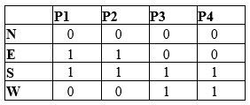
Testing connectivity:
Button A pressed (N) – Coax centre connects to SE element, coax braid connected to SW element, the capacitor is connected between NE & NW elements.
Button B pressed (E) – Coax centre connects to NW element, coax braid connected to SW element, the capacitor is connected between NE & SE elements.
Button C pressed (S) – Coax centre connects to NW element, coax braid connected to NE element, the capacitor is connected between SE & SW elements.
Button D pressed ![]() – Coax centre connects to NE element, coax braid connected to SE element, the capacitor is connected between SW & NW elements.
– Coax centre connects to NE element, coax braid connected to SE element, the capacitor is connected between SW & NW elements.
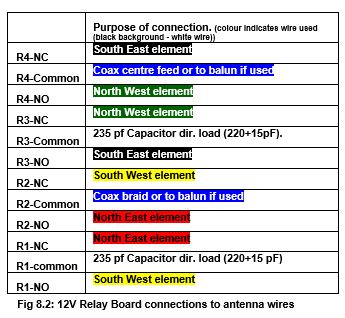
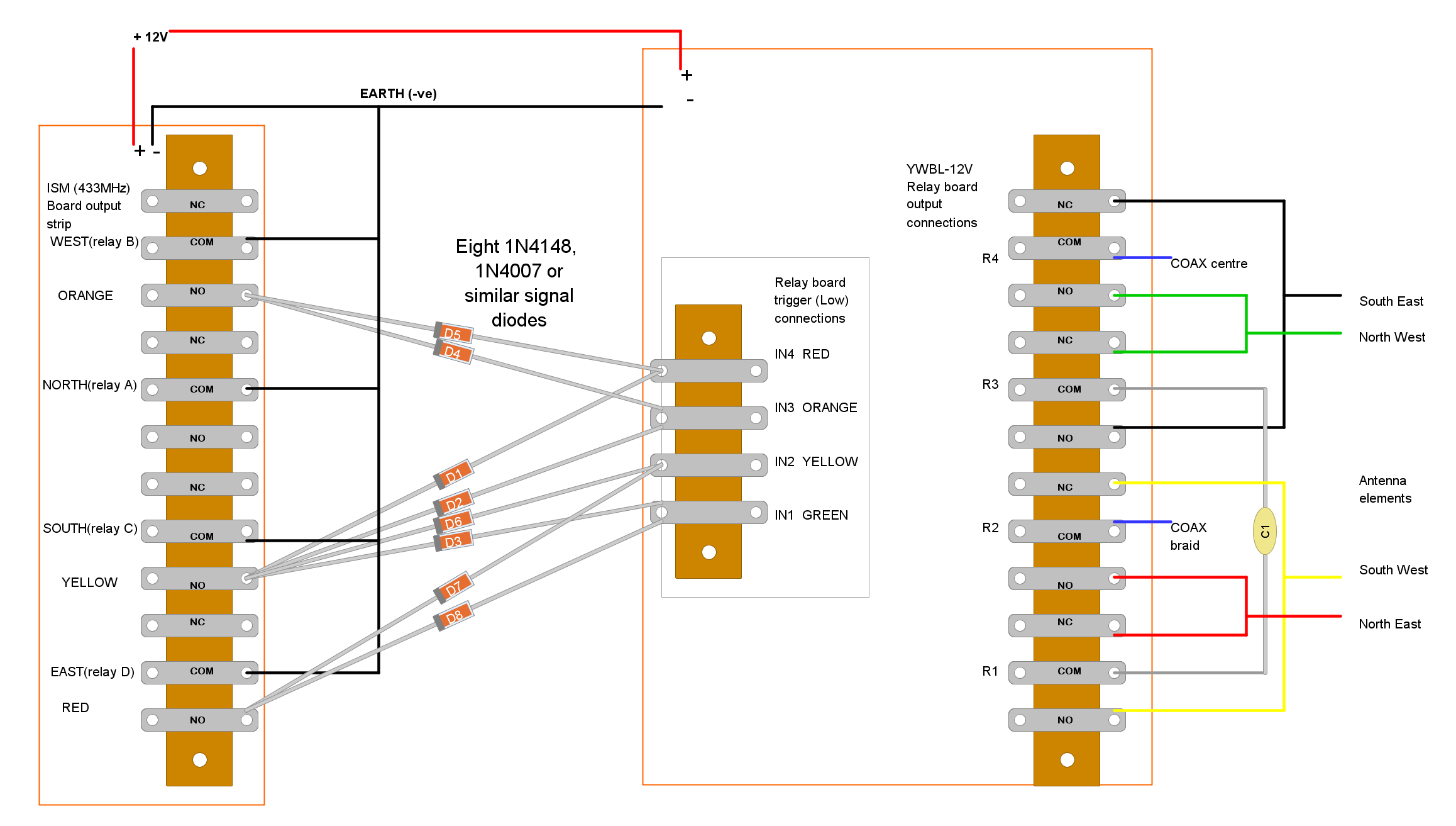
Fig 8.3: Interconnection diagram
Further improvements.
As I now have a working solution, the technical issues are resolved, and operationally, using the key fob is a far better solution than relying upon a smartphone app. Also, rather than placing a battery on the feed-point board, I have switched to using a Video camera cable, which has a coax cable and a DC power cable in one cable. This has been tested and is using the same 12v supply that is used for the radio through this cable to the board works without issues, and makes this one less thing to worry about. It uses RG59 (75 Ohm) cable, but that impedance compromise is IMHO worthwhile for the simplification it brings with it.
This solution, although working well, is not perfect though.
- The feed point board is not protected from the weather, or the boards on it protected from being knocked.
- The board is too large to go inside my rucksack as I would prefer, and has to be carried separately.
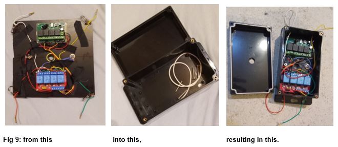
So, we need to address these points by placing the two boards, interconnecting cables and power and coax access into one protected, smaller box. Both the top and bottom of the box provide support to the mast, and the existing holes in the flanges on the box provide the anchor points for the elements/support guys. So, we need to go ….
Bill of materials (BOM) for this latest version (including mast and cords):
- Box with flanges ~ 160mm x 90mm x 50mm (or larger) (€9.99): https://www.amazon.de/dp/B0BZCLDWR5?ref=ppx_yo2ov_dt_b_product_details&th=1
- Rubber-centred washers (USIT Hydraulic M14) to sit feed point on the mast – 2 used (€5 for 10): https://www.ebay.de/itm/185917457777
- Switching board (12v) used to switch elements (€ 9.19): https://www.amazon.de/dp/B07QL1TFFW?ref=ppx_yo2ov_dt_b_product_details&th=1
- ISM receiver & relay board used to trigger antenna switching board with 4-button key fob (€ 8.92): https://www.aliexpress.com/item/1005002117577055.html?
- Simple “hook-up wire for elements and board wiring (€ 13.99): https://www.amazon.de/dp/B0B6ZV2263?ref=ppx_yo2ov_dt_b_product_details&th=1
- RG59 siamese security camera cable (combined 75Ω coax/12vDC supply cable with BNC and 12v plugs) (€5.16 for 10m): https://www.aliexpress.com/item/1005005255786060.html?
- Trap kit (4 traps needed per additional band) (€5 per trap kit): https://www.hfkits.com/product/antenne-trap-kit/
- 12V DC (barrel connector) power and BNC socket – from your usual supplier (or junk box). (If you don’t have any DC sockets here’s 10 for €7) https://www.amazon.de/-/en/Socket-2-Pin-Power-Panel-Connector/dp/B09PD6J4BN/
- Signal diodes (IN4148, IN4007 or similar) 8 needed – from your usual supplier (or junk box).
- 7m high support mast (€23.02): https://www.zite.de/stipprute-fiberglas-material-spitzen-endring-zite-fishing-p-475.html
- Pegs & guy cords for 20m model (longer cords needed for 10m only antenna (€7.99): https://www.amazon.de/-/en/Diameter-Tensioners-Camping-Suitable-Tarpaulin/dp/B08J84KTGQ/
- Rings & carabiners to make elements detachable (€6.99): https://www.amazon.de/gp/product/B0BCP21KDT/

Fig 10: Target achieved – complete HF station using the HF beam, radio, log, seating, pack-up, antenna support mast, pegs & base, PLUS second back-up (HF-PRO2 plus tripod) antenna all in or on my 40L backpack. Truly PORTABLE with an HF 2-element direction switchable multi-band beam!
DESIGN Change Number 4A – Adding 40 metres.
While not really a design change, adding 40 metres to the antenna has some more things to be considered. For this change, the addition was made to the linked dipole elements using the manually switched feed point board. Such an addition should also be possible to the trapped design by adding four traps wound for 20 metres.
When we add extra wire to all elements to make each element a quarter wave long on 7 MHz, the wire is longer than the guy cord that I use to fasten it (and the links) to. Coiling up or hanging loose the wire so that it fits the existing guy cords makes the antenna do all kinds of weird things on the analyser and as such, is not a solution. The guy cords were extended by 1.5m. This means that the angle at the apex was 55° rather than 56°, but the change is negligible, and a friend, Rob DM1CM, modelling this antenna proved that the angle, although quoted everywhere as needing to be 56°, is not actually critical to the operation of the antenna, as long as all elements come down at the same angle.
The other change I made was to the capacitor that defines the director element. I added two banana plug sockets on the board, wired across the current 235 pF capacitor, where I plugged in a 240pF Mica capacitor, getting “close to” the calculated 450 pF needed. By having this plug-in capability, I can also, in the future, test the VK6VZ suggestion of increasing the capacitance by 30% to give extra gain.
The revised antenna was tested from a local park, and while it worked on 40m, there was no directivity at all from the antenna. A further favour from Rob and I could see that at the heights that I was able to put the antenna up at, the radiation pattern was omnidirectional and the take-off angle was around 60° to the ground.
Further modelling showed that for this design to be a directional antenna, the feed point would have to be at least 20 metres off the ground, at which point the take-off angle also lowered to about 30°.
So, my conclusion is that this design is
NOT SUITABLE for a 40-metre portable Beam.
(Take a look at the VP2E antenna for a 40m directional antenna).
REFERENCES
- 2-element Single Mast Wire Beam with 4 Switchable Directions – Chavdar Levkov Jr. LZ1ABC and Chavdar Levkov LZ1AQ: lz1aq.signacor.com/docs/2-element-single-mast-wire-beam.php
- QST Article “Inverted V Wire Yagi with Switchable Pattern Rotation for 14 MHz” from Ashraf Abuelhaija and Klaus Solbach, DK3BA (PDF): uni-due.de/imperia/md/images/hft/abuelhaija_inverted_v_wire_yagi.pdf and their paper from Kassel & Duisburg University: http://www.researchgate.net/publication/254028014_Six-beam_reconfigurable_wire_antenna
Ed Durrant DD5LP / VK2JI / G8GLM Version 2.2 23rd October 2024.

You must be logged in to post a comment.